Pdi-selection, Table 2 positions of the pdi-selector, Figure 7 pdi-selection area – BECKHOFF EL9800 Basisplatine User Manual
Page 14: 3 pdi-selection
Product overview
12
EL9800
Pin number
Digital IO
SPI
8/16bit sync./as. µC
42
N.C.
N.C.
nBHE
43
LATCH_IN
N.C.
IRQ
44
SYNC[1]/LATCH[1]
45
GND
46
OE
N.C.
nTA/nBUSY
47
N.C.
48
VCC
49
3.3V Out
50
VCC (5V Input)
51
CLK25_OUT
N.C.
A[15]
52
OE_CONF
GPO[0]
A[14]
53
Not Used
54
Not Used
55
Not Used
56
Not Used
Note
Usage of the FB1111-0142 with differing PDIs
The usage of the FB1111-0142 with the PDIs SPI and µ-Controller is only supported
for evaluation purposes in combination with the EL9800 base board. Therefore the
pinout of the headers J202 and TP202 is not supported in these cases.
In custom devices the usage of postage stamps with the appropriate PDI is recom-
mended.
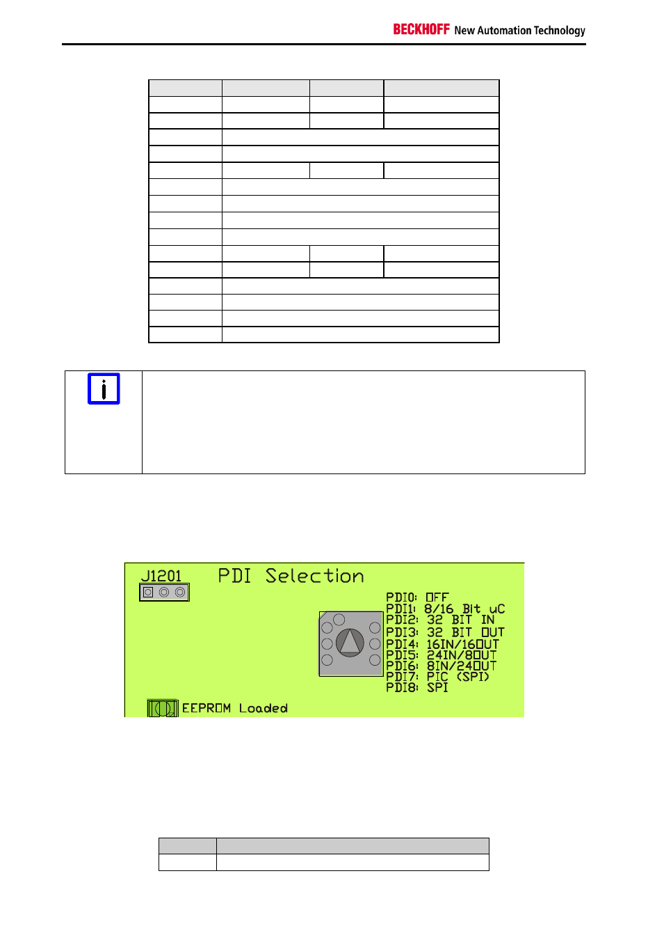
2.3 PDI-Selection
Figure 7 PDI-Selection Area
Selection of the different PDIs on the EL9800 takes place using a rotary selector in the PDI-Selection
Area. Based on the four physical PDIs all in all eight logical PDIs are selectable over the PDI-Selector.
The selector positions listed below activate the corresponding PDI shown in Table 2
Table 2 Positions of the PDI-Selector
Position Process data interface
0
OFF