32 bit digital-pdi-interface, Table 5 port configuration of the digital pdi, Figure 11 digital io pdi-interface – BECKHOFF EL9800 Basisplatine User Manual
Page 19: 5 32 bit digital-pdi-interface
Product overview
EL9800
17
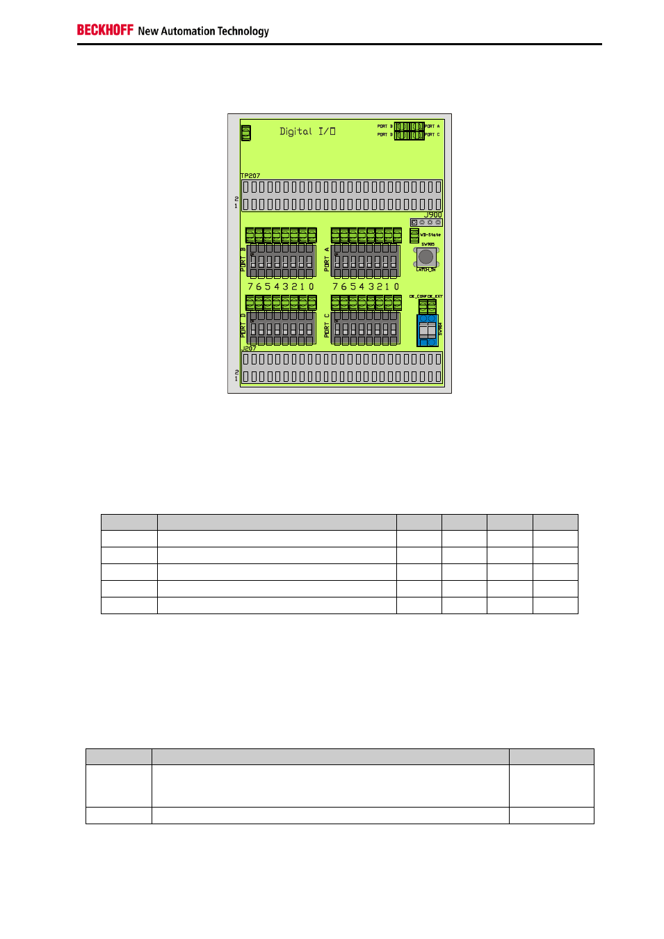
2.5 32 Bit Digital-PDI-Interface
Figure 11 Digital IO PDI-Interface
Additional to the input and output signals the digital process data interface contains configuration and
status signals. Using the PDI-Selector byte wise configuration of the 32 digital signals is supported. The
following combinations are selectable (Table 5).
Table 5 Port configuration of the digital PDI
Position Process Data Interface
Port A Port B Port C Port D
2
32 Bit digital Interface - 32 Inputs
IN
IN
IN
IN
3
32 Bit digital Interface - 32 Outputs
OUT
OUT
OUT
OUT
4
32 Bit digital Interface - 16 Inputs / 16 Outputs
IN
IN
OUT
OUT
5
32 Bit digital Interface - 24 Inputs / 8 Outputs
IN
IN
IN
OUT
6
32 Bit digital Interface - 8 Inputs / 24 Outputs
IN
OUT
OUT
OUT
Four LEDs in the top right edge of the digital PDI area are showing the configuration of the data bytes.
The LEDs are active, if the corresponding Byte (Port A to Port D) is configured as an output from the
EtherCAT postage stamps view. Furthermore eight LEDs and Switches are assigned to each port, for
input and output purposes respectively.
The lower right section of the digital PDI interface is assigned to configuration and status indication of the
digital PDI. The Switch SW904 configures the signals OE_CONG and OE_EXT according to Table 6.
Table 6 Definition of the OE_CONF and OE_EXT signals
Signal
Function
Polarity
OE_CONF Output Configuration
– Behavior of the output signals in case of a
falling edge of the WD_STATE signal. Or when OE_EXT is low re-
spectively
Positive
OE_EXT
Output Enable
– Enables the output of the output signals.
Positive
Manual latching in of the input data can be controlled by activating the switch SW905. Furthermore the
state of the EtherCAT-Slave-
Controllers (ESC) watchdog is indicated by the “WD-State” LED is active. In