AMETEK SGI Series User Manual
Page 95
Sorensen SGI Series
Calibration and Verification
M550221-01 Rev AA
3-43
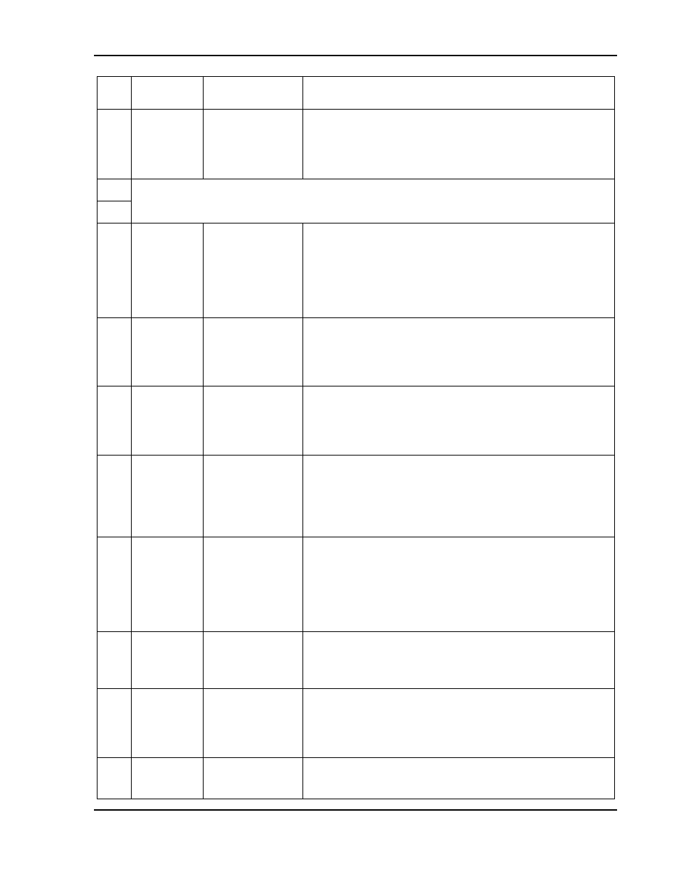
Pin Reference
Electrical
Parameters
Functional Description
11
ISET
*
Zout ~ 100
Monitor signal for front panel current potentiometer setpoint:
0-5 VDC = 0-100% of full-scale setpoint. Minimum
recommended load resistance is 100 k
Signal return is Pin
J1-6 (COM). Circuit is electrically connected to the output
power negative terminal.
12
Not Used
13
14
ISO
TTL/CMOS
Zin ~ 900
in
series with anode
of opto-isolator
LED
Isolated remote control input for output on/off with a logic
signal: a logic-high, 5 VDC TTL/CMOS signal will enable
(turn-on) the output of the supply, and a logic-low signal
disables (turns off) the output. This control input is optically
isolated from the output power negative terminal of the power
supply (up to 500 VDC). Signal return is Pin J1-2 (ISO RTN).
See Section 3.13.
15
VP 10V
Zin ~ 20 k
Remote control input for voltage programming using a voltage
source: 0-10 VDC = 0-100% of full-scale output voltage. Do
not exceed an input of 25 VDC. Signal return is Pin J1-4 or
Pin J1-20 (VP RTN). Circuit is electrically connected to the
output power negative terminal. See Section 3.11.
16
IP 10V
Zin ~ 20 k
Remote control input for current programming using a voltage
source: 0-10 VDC = 0-100% of full-scale output current. Do
not exceed an input of 25 VDC. Signal return is Pin J1-4 or
Pin J1-20 (VP RTN). Circuit is electrically connected to the
output power negative terminal. See Section 3.10.
17
FAULT
Zout ~ 1 k
Output signal for indicating a fault state: a logic-high state
(approximately +10 VDC) indicates a fault has occurred in a
power module, such as overtemperature, undervoltage of AC
input, or converter failure; front panel Fault LED will also be
lit. Signal return is Pin J1-6 (COM). Circuit is electrically
connected to the output power negative terminal.
18
S/D FAULT
Zout ~ 100
Output signal for shutdown/fault state: a logic-high state
indicates shutdown produced by an OVP condition, Power-
On-Reset (POR), remote disable, or housekeeping supply
fault. An 8 VDC minimum output signal is provided into a
load of 10 k
load. Signal return is Pin J1-6 (COM). Circuit is
electrically connected to the output power negative terminal.
See Section 3.13.3.
19
V MON
Zout ~ 100
Monitor signal for output voltage: 0-10 VDC = 0-100% of full-
scale output voltage. Minimum recommended load resistance
is 100 k
Circuit return Pin J1-6 (COM). Circuit is electrically
connected to the output power negative terminal.
20
VP RTN
Zin ~ 10 k
Voltage programming signal return to be used with Pins J1-9,
J1-15 or J1-21; also must be externally connected to Pin J1-6
(COM) signal return when voltage programming is utilized.
Circuit is electrically connected to the output power negative
terminal.
21
VP RES
*
1mA current
source with
compliance
Current source of 1 mA for remote voltage programming
using a resistance connected to signal return Pin J1-4 or
Pin J1-20 (VP RTN): 0-5 k
Ω = 0-100% of full-scale output