Figure 3 – Zilog EZ80F91GA User Manual
Page 21
UM024502-1012
Connecting the ZGATE Embedded Security
ZGATE Embedded Security Development Kit
User Manual
9
1. Ensure that the following default jumper settings are configured (see
108 for reference):
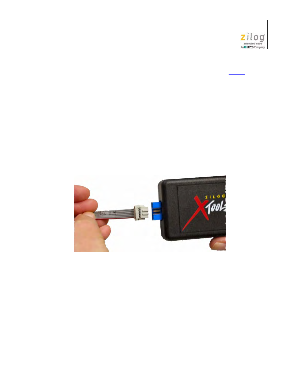
2. Connect one end of the 6-circuit ribbon cable provided in your Kit to the USB Smart
Cable unit, ensuring that the ribbon’s male connector is aligned correctly with the
female connector on the unit, as indicated by the red stripe in Figure 3.
3. Connect the other end of the ribbon cable to Debug Connector J1 on the Development
Board. Ensure that Pin 1 on the ribbon cable is aligned with Pin 1 on the target con-
nector, as highlighted in Figure 4.
J11
OUT
J12
1–2
J26
IN
J25
2–3
J24
1–2
J23
1–2
Figure 3. Connecting the Six-Conductor Ribbon Cable to the Serial or USB Smart Cable
- S3F94C8 (11 pages)
- S3F80QB (29 pages)
- S3F8S19 (38 pages)
- Z51F6412 (96 pages)
- Z51F6412 (54 pages)
- Z51F6412 (55 pages)
- Z16F6411 (216 pages)
- EZ80F93 (11 pages)
- Z16F6411 (20 pages)
- ZMOT0BSB (314 pages)
- ZMOT0BSB (582 pages)
- EZ80F93 (13 pages)
- Z8F083A (14 pages)
- Z8F082A (18 pages)
- Z8F2480 (17 pages)
- Z8F082A (15 pages)
- Z8F0822 (17 pages)
- Z8F6423 (83 pages)
- Z8F2480 (18 pages)
- Z8F2480 (19 pages)
- Z8F6423 (27 pages)
- Z8F6423 (18 pages)
- Z8F6482 (50 pages)
- EZ80L92 (79 pages)
- EZ80F91GA (469 pages)
- EZ80F915 (411 pages)
- EZ80F91NAA (34 pages)
- EZ80F91 (41 pages)
- EZ80L92 (40 pages)
- EZ80L92 (26 pages)
- EZ80L92 (10 pages)
- eZ80F92 (87 pages)
- ZUSBOPTS (38 pages)
- ZUSBOPTS (59 pages)
- Z16FMC6 (520 pages)
- Z8FMC16 (26 pages)
- Z16FMC6 (41 pages)
- Z16FMC6 (8 pages)
- Z16FMC6 (26 pages)
- ZMOT1AHH (25 pages)
- ZMOT0BSB (34 pages)
- EZ80F915 (78 pages)
- EZ80190 (87 pages)
- EZ80L92 (86 pages)