Vectronics VEC-4001K User Manual
Page 22
VEC-4001K Owner’s Manual
Professional Function Generator
22
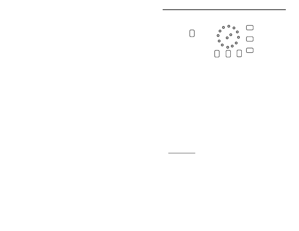
R4
R5
R6
R7
R8
R9
R10
10
0
10
1
10
2
10
3
10
4
10
5
Low Set
Bottom View
To check the generator's output signal, set an oscilloscope to measure 10 Vpp
with a 1 mS sweep rate. Connect scope input to Output. Set the generator's DC
Offset, Amplitude, and Frequency for 12:00, and switch Multiplier to 10
2
.
3. Set Waveform for sinewave and check output trace.
4. Set for triangle and check output trace.
5. Set for squarewave and check output trace.
6. Adjust Amplitude up and down observing change.
The generator's peak-to-peak output should roughly coincide with scale markings
on the Amplitude control. If you fail to obtain the correct waveforms, check
switch wiring and PC-board connections. If amplitude is substantially
inaccurate, check for errors around R2.
Frequency Calibration: You may calibrate your generator using an audio
frequency counter or an oscilloscope with a calibrated sweep. Note that some
wide-range RF counters may not perform well at audio frequencies below 100
kHz.
A. Counter Method: Connect counter to Output terminals. Set DC Offset and
Amplitude at 12:00. Set Frequency to 10 (CW) and Waveform to square.
1. Set Multiplier to 10
5
and adjust R9 for 1 MHz output.
2. Switch Multiplier to 10
4
and adjust R8 for 100 kHz output.
3. Switch Multiplier to 10
3
and adjust R7 for 10 kHz output.
4. Switch Multiplier to 10
2
and adjust R6 for 1 kHz output.
5. Switch Multiplier to 10
1
and adjust R5 for 100 Hz output.
6. Switch Multiplier to 10
0
and adjust R4 for 10 Hz output.*
7. Set Frequency control to 1 (CCW).
8. Switch Multiplier back to 10
2
and adjust R10 for 100 Hz output.