Vectronics VEC-4001K User Manual
Page 16
VEC-4001K Owner’s Manual
Professional Function Generator
16
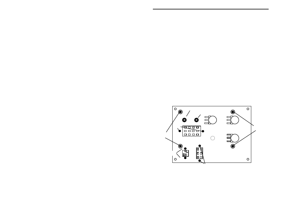
! ! 76. Cut to 1 3/4" and prepare jumper. Install at JMP3 and solder.
! ! 77. Cut to 1 3/4" and prepare jumper. Install at JMP1 and solder.
! ! 78. Cut to 1" and prepare jumper. Install at JMP2 and solder.
Finally, locate the remaining three (3) ICs. Each has a round key or a notch at
one end to indicate correct orientation. Before installing, inspect carefully and
confirm all pins are straight. During installation, align pins carefully and insert
slowly to avoid bending or folding. Observing orientation, install as follows:
! ! 79. Install the LM318 op-amp IC at U2.
! ! 80. Install the LM358 op-amp IC at U3.
! ! 81. Install the MAX038CPP function-generator IC at U1.
All components should now be installed on your PC board. Next, you'll install
switches, controls, and jacks on the front panel and wire them to the PC board.
Before starting this procedure, give the PC board a thorough inspection.
This is the final phase of construction. To begin, position the front panel with
the silk-screened side down, as shown below. Locate the remaining switches,
jacks, and potentiometers. Install as follows:
Black binding post
Red binding post
10K pot
10K pot
10K pot
4P3T Switch SW3
2P2T Switch
SW1
Power Jack
J1
J3
J2
R2
R3
R1
2-56
4-40
4-40
Spacer
6-32
Spacer
6-32
Find two (2) binding posts. When installing, use care not to overtighten--plastic
threads may be damaged by excessive torque.
! ! 82. Install the black binding post at J3.
! ! 83. Install the red binding post at J2.