Vectronics VEC-4001K User Manual
Page 18
VEC-4001K Owner’s Manual
Professional Function Generator
18
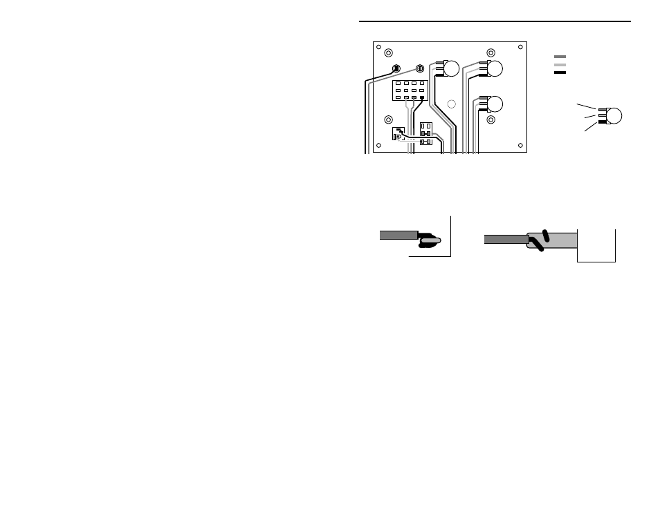
SW3
SW1
J1
J3
J2
R2
R3
R1
Red
Yellow
Black
Color Code
Top or "clockwise"
Middle or "center"
Bottom or "counter-clockwise"
terminal (CTR)
terminal (CW).
terminal (CCW)
The remaining wires will be installed one control at a time, and twisted together
for routing to the PC board. To prepare, cut each to the specified length and
remove 1/4" insulation from each end. Wrap tab or lug connections before
soldering (see following diagram):
Tab
Lug
! ! 97. Begin by wiring R1. Cut and prep a set of 6" red, yellow, and black
lead. Find R1 and install as follows:
! ! 98. Attach a red lead to the top (CW) terminal of R1 and solder.
! ! 99. Attach a yellow lead to the center (CTR) terminal of R1 and solder.
! ! 100. Attach a black lead to the bottom (CCW) terminal of R1 and solder.
! ! 101. Twist all three wires together, leaving about 1 1/2" unwound at the
far end.
! ! 102. Cut and prep another set of 6" wires (red, yellow, and black). Find
R2.
! ! 103. Attach a red lead to the top (CW) terminal of R2 and solder.
! ! 104. Attach a yellow lead to the center (CTR) terminal of R2 and solder.
! ! 105. Attach a black lead to the bottom (CCW) terminal of R2 and solder.
! ! 106. Twist all three wires together, leaving about 1 1/2" unwound at the
far end.