Vectronics VEC-4001K User Manual
Page 10
VEC-4001K Owner’s Manual
Professional Function Generator
10
STEP-BY-STEP CONSTRUCTION
In these instructions, when you see the term install, this means to locate, identify,
and insert the part into its mounting holes on the PC board. This includes pre-
bending or straightening leads as needed so force is not required to seat the part.
Once a component is mounted, bend each lead over to hold it in place. Use
sharp side-cutters to clip off excess lead length before soldering. Make sure
trimmed leads don't touch other pads and tracks, or a short circuit may result:
Good
Not Good
The term solder means to solder the part's leads in place, and to inspect both (or
all) solder connections for flaws or solder bridges. Nip off excess protruding
leads with a sharp pair of side cutters.
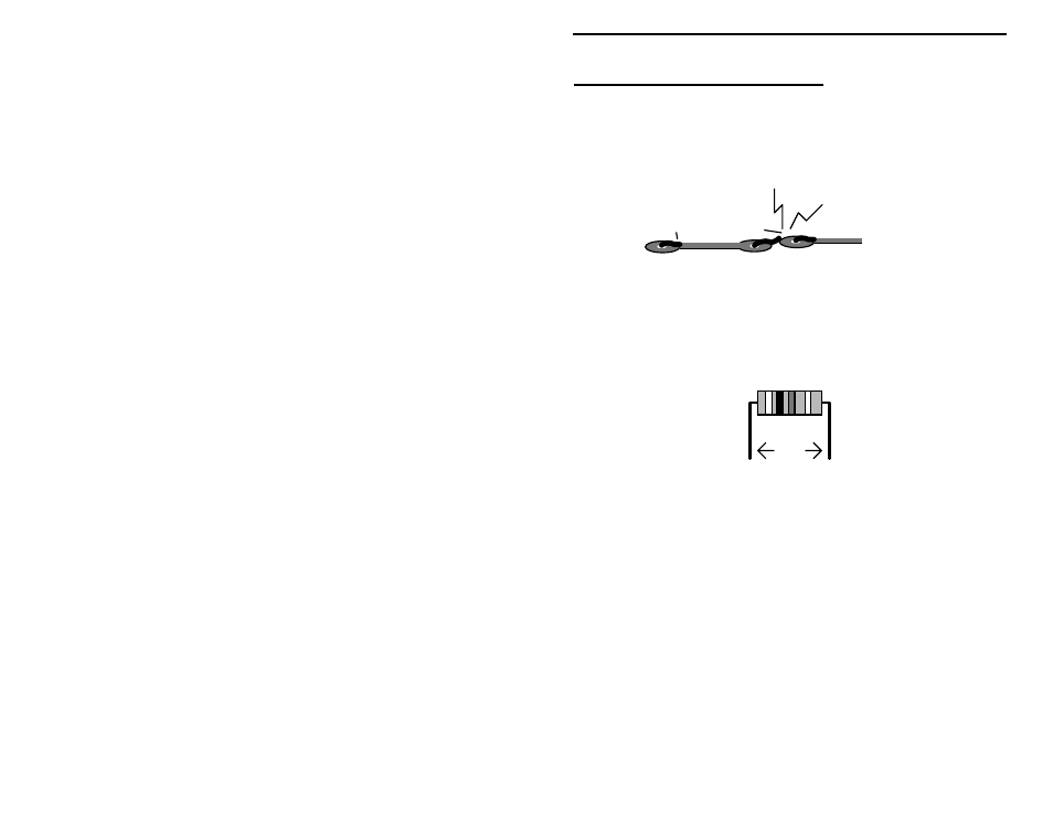
This kit has 25 fixed-value resistors. Mount these now, starting with the smallest
value and moving to the largest. Before mounting each one, carefully bend both
leads close to the resistor body to form right-angles, as shown below:
.4"
! ! 1.#Find a 51 Ohm resistor (green-brown-black). Install at R16 and
solder.
Locate two (2) 100 Ohm resistors (brown-black-brown).
! ! 2.#Install a 100 Ohms at R25 and solder.
! ! 3.#Install a 100 Ohms at R26 and solder.
! ! 4.#Find a 680 Ohm resistor (blue-gray-brown). Install at R15 and
solder.
! ! 5.#Find a 1K resistor (brown-black-red). Install at R19 and solder.
Locate eight (8) 1.6K resistors (brown-blue-red).
! ! 6.#Install a 1.6K at R28 and solder.
! ! 7.#Install a 1.6K at R29 and solder.
! ! 8.#Install a 1.6K at R30 and solder.