Vectronics VEC-4001K User Manual
Page 11
VEC-4001K Owner’s Manual
Professional Function Generator
11
! ! 9.#Install a 1.6K at R31 and solder.
! ! 10.#Install a 1.6K at R32 and solder.
! ! 11.#Install a 1.6K at R33 and solder.
! ! 12.#Install a 1.6K at R34 and solder.
! ! 13.#Install a 1.6K at R35 and solder.
! ! 14.#Find a 2K resistor (red-black-red). Install at R17 and solder.
Locate two (2) 3K resistors (orange-black-red).
! ! 15.#Install a 3K at R13 and solder.
! ! 16.#Install a 3K at R21 and solder.
Locate four (4) 12K resistors (brown-red-orange).
! ! 17.#Install a 12K at R11 and solder.
! ! 18.#Install a 12K at R12 and solder.
! ! 19.#Install a 12K at R14 and solder.
! ! 20.#Install a 12K at R20 and solder.
Locate two (2) 22K resistors (red-red-orange).
! ! 21.#Install a 22K at R24 and solder.
! ! 22.#Install a 22K at R27 and solder.
! ! 23.#Find a 24K resistor (red-yellow-orange). Install at R18 and solder.
Locate two (2) 27K resistors (red-violet-orange).
! ! 24.#Install a 27K at R22 and solder.
! ! 25.#Install a 27K at R23 and solder.
This completes installation of the 25 fixed-value resistors (trimpots and
potentiometers will be installed later). Take a moment to confirm each fixed-
value resistor is positioned in the right location on the PC board.
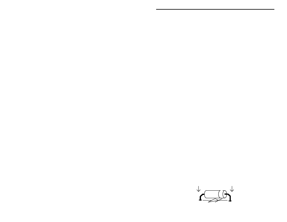
Next, we’ll install the kit’s diodes. . Diodes are polarized and must be oriented
correctly in order to work. The banded end of the diode should align with the
single-lined end of the diode symbol on the PC board (see following diagram).