Controls & functions, Rear – TVLogic LVM-174W User Manual
Page 12
12 Multi Format LCD Monitor
Connector Composite Component
S-Video
1
CVBS1
Y
G
Y
2
CVBS2
Pb
B
No Con.
3
CVBS3
Pr
R
C
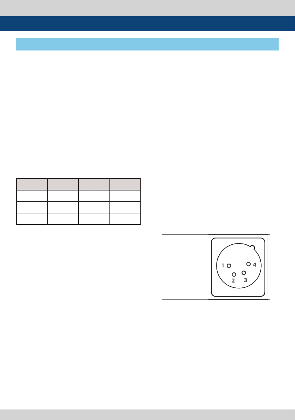
DC IN socket
1,2 : GND
3,4 : +24V
●
●
CVBS1/Y/G/S-Y (BNC) IN/OUT
- Signal input terminal used to feed the
monitor Composite1, RGB G, Component Y,
and S-Video Y signals.
●
●
CVBS2/Pb/B (BNC) IN/OUT
- Signal input terminal used to feed the
monitor Composite2, RGB B and Component
Pb signals.
●
●
CVBS3/Pr/R/S-C (BNC) IN/OUT
- Signal input terminal used to feed the
monitor Composite3, RGB R, Component Pr
and S-Video C signals.
Analog Video input connection method.
●
●
HDMI
- Signal input terminal for HDMI signal.
●
●
[DVI-I] (DVI-I)
- Signal input terminal for DVI DIGITAL or DVI
ANALOG signal.
●
●
SDI IN-A/SDI IN-B (BNC)
- Signal input terminal for SD/HD/3G-SDI .
●
●
SDI-OUT (BNC)
- HD/SD/3G SDI Signal Output which is input
through [SDI-IN] terminal.
●
●
AUDIO IN (Phone Jack)
- Audio input terminal for External Audio
signal.
●
●
AUDIO OUT (Phone Jack)
- Used for Output of Disembedded Audio
signal or the Audio signal input through
Audio In terminal.
●
●
LAN (RJ-45)
- Used to control the monitor with protocol
provided by TVLogic or Network
●
●
[REMOTE] (RJ-45)
- Provides connection to control
equipment(parallel switch) for external
monitor control.
- Features can be changed in the REMOTE
section of OSD menu.
●
●
[RS422 IN/OUT] (RJ-45)
- Used to control the monitor with protocol
provided by TVLogic or to support Dynamic
UMD(TSL protocol).
●
●
DC IN (XLR, 4 pins)
- Used to supply DC power for DC 24V.
●
●
[AC IN]
- Used to supply AC power; 100V~240V
50/60Hz input range.
●
●
POWER S/W
- Power Switch
When using the product make sure to ground
before connecting the input signal line.
The unit may not operate properly if the
input line is connected before the GND is
connected.
Rear
3. Controls & Functions