Wiring the fault alarm contacts 3.5 – KBC Networks ESML8P-PC2 User Manual
Page 18
Manual-ESML8P-PC2_Series-Rev1211
Copyright © KBC Networks Ltd.
Page 18 of 110
www.kbcnetworks.com
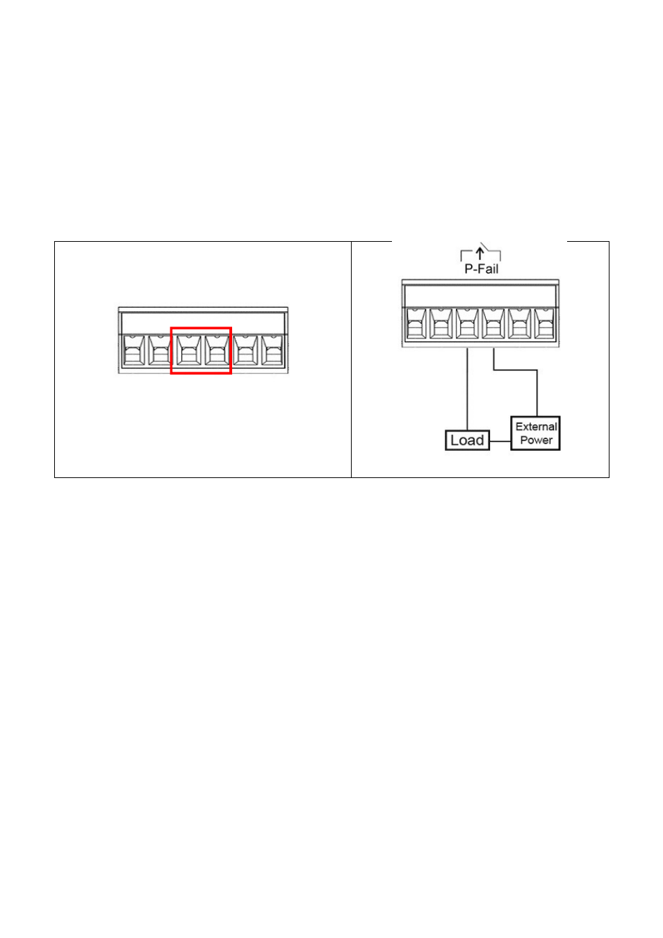
Wiring the Fault Alarm Contacts
3.5
The fault alarm plugs are in the middle of the terminal block, as the left picture shown below.
With a Normally Closed circuit formed by wiring with an external power and a warning device (a
buzzer or a flashing LED), system will detect the fault states including the port linking failure
(managed industrial switch only) and the power failure. Please refer to the right picture below, a
wiring example for the fault alarm application.
Terminal Block Plugs for Fault Alarm
Contacts
Fault Alarm Wiring Example
24Vdc, 1A
Resistance
See also other documents in the category KBC Networks Computer Accessories:
- FTL1-S1A-B-MSE (10 pages)
- MCG1-S2-BS (8 pages)
- ThruLink SP (2 pages)
- VPS Solar Power Kits (12 pages)
- MiniLink (15 pages)
- MeshII (2 pages)
- Mesh2HT (59 pages)
- WES (19 pages)
- WES (18 pages)
- WES2HT 17dBi Point-to-Point Client / Host 5GHz (2 pages)
- WES2HT 2/5dBi Point-to-Multipoint Host with PoE (2 pages)
- WES2HT 9dBi Multipoint Host (2 pages)
- WESII 9dBi to 9dBi Kit (5 pages)
- WESIIKT V221 17dBi to 17dBi Kit (4 pages)
- H.264 Encoder (2 pages)
- H.264 Encoder (49 pages)
- MPEG-4 Decoder (2 pages)
- MPEG-4 Encoder (2 pages)
- MPEG4 Decoder (29 pages)
- MPEG4 Encoder (33 pages)
- WES2HT (142 pages)
- ESML3-FL2-D4 (18 pages)
- ESML6-FL2 (64 pages)
- ESUL6-FL2 (20 pages)
- ESML6-P3 (17 pages)
- ESML6-P3 (49 pages)
- ESML6-P3 (51 pages)
- WESII (141 pages)
- ESUG4P-PG2 (15 pages)
- ESUG8P (14 pages)
- ESUL4-FL1 (17 pages)
- ESUL5 (15 pages)
- ESUL8 (14 pages)
- ESUL5P (14 pages)
- EE2CL (19 pages)
- ESUL8P-PC2 (15 pages)
- EE1CL (17 pages)
- EE1R3 (12 pages)
- FCHA1-M1T-R-WSB (13 pages)
- FDVA2-S2T-R-WSC (11 pages)
- Compact Transceiver (36 pages)
- FDVA4-DB1-S1T-R-WSC (14 pages)
- 3U Chassis Transceiver (40 pages)
- FDVA4-S1T-R-WSC (11 pages)