33 stac6 hardware manual – Applied Motion STAC6-C User Manual
Page 33
33
STAC6 Hardware manual
920-0029 Rev. C
5/2/2012
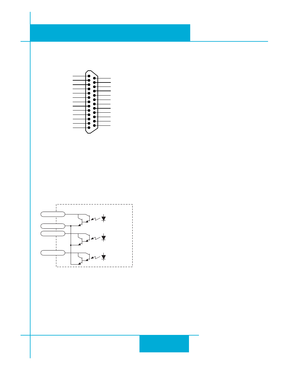
Connecting Digital Outputs on the IN/OUT1 connector
Front View
X COMMON
X7 / CW Limit
X3 / Enable
X5
X4 / Alarm Reset
Analog IN-
Analog IN+
X2 / DIR-
X2 / DIR+
X1 / STEP +
X1 / STEP -
GND
GND
+5V OUT
Y COMMON
Y3 / FAULT
Y2 / MOTION
Y1 / BRAKE
� �
� �
� �
� �
� �
� �
� �
� �
� �
�
�
�
�
�
�
�
�
�
� �
� �
� �
� �
� �
� �
� �
X6 / CCW Limit
IN/OUT 1
+5V OUT
+12V OUT
GND
GND
All STAC6 drives feature three digital outputs on the IN/OUT 1 connector:
Y1/Brake: controls an electric brake relay, automatically releasing and engaging as the drive requires
Y2/Motion: indicates that the drive has achieved a desired goal, such as a target position
Y3/Fault: closes when a drive fault occurs. The red and green LEDs will flash an error code.
inside STAC-6
14
17
15
16
Y3/FAULT
Y2/MOTION
Y COM
Y1/BRAKE
These outputs can be used to drive LEDs, relays and the inputs of other electronic devices like PLCs and
counters. These outputs can only sink current.
The COM terminal must be tied to power supply (-).