Wiring inputs and outputs, 24 stac6 hardware manual – Applied Motion STAC6-C User Manual
Page 24
24
STAC6 Hardware manual
920-0029 Rev. C
5/2/2012
Wiring Inputs and Outputs
The STAC6 drives come with a number of inputs and outputs for interfacing to external control hardware:
•
High speed digital inputs for step & direction commands or encoder following, 5V logic. These
inputs, X1/STEP and X2/DIR, are available on all models. They can also be used to connect
sensors and other types of devices. Connections to these inputs can be sourcing, sinking or
differential.
•
Lower speed digital inputs for other signals, 12 - 24 volt logic, accepting sourcing, sinking or
differential signals. All STAC6 models have 5 of these inputs on the IN/OUT1 connector.
STAC6-QE and Si models only have a total of 13 of these inputs, 5 on the IN/OUT 1 connector and
8 on the IN/OUT 2 connector.
•
Analog inputs for analog speed and positioning modes, included on all drives. Can be configured
for 0-10V, 0-5V, ±10V or ±5V, with or without offset. The STAC6-QE and Si models have an extra
analog input rated at 0-5VDC - for use in SCL and Q applications only.
•
Digital Outputs rated at 30V, 100mA. There are three outputs on IN/OUT1, which is present on
all models. STAC6-QE and Si models only have an additional 4 digital outputs on the IN/OUT2
connector.
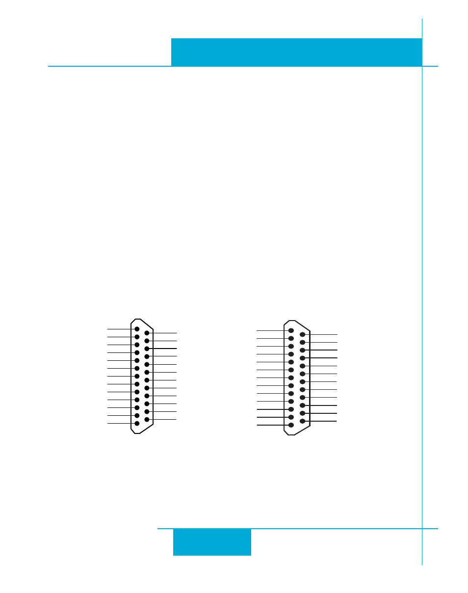
Connector Pin Diagrams
Front View
X COMMON
X7 / CW Limit
X3 / Enable
X5
X4 / Alarm Reset
Analog IN-
Analog IN+
X2 / DIR-
X2 / DIR+
X1 / STEP +
X1 / STEP -
GND
GND
+5V OUT
Y COMMON
Y3 / FAULT
Y2 / MOTION
Y1 / BRAKE
� �
� �
� �
� �
� �
� �
� �
� �
� �
�
�
�
�
�
�
�
�
�
� �
� �
� �
� �
� �
� �
� �
X6 / CCW Limit
IN/OUT 1
+5V OUT
+12V OUT
GND
GND
18
17
16
15
14
13
12
11
10
9
8
7
6
5
4
2
3
1
19
20
21
22
23
24
25
+5V
Out 1-
Out 2+
Out 1+
Ain Com
N/C
Ain 1
IN 8-
COM
IN 5
IN 6
IN 7+
IN 8+
IN 7-
IN 4
IN 1
COM
IN 2
COM
IN 3
Out 2-
Out 3+
Out 3-
Out 4+
Out 4-
IN/OUT 2
IN/OUT1 connector, this connector
is present on all models
IN/OUT2 connector, this connector
is present on Si and QE models