31 stac6 hardware manual, Connecting limit switches to the stac6 drive, Wiring a mechanical limit switch – Applied Motion STAC6-C User Manual
Page 31
31
STAC6 Hardware manual
920-0029 Rev. C
5/2/2012
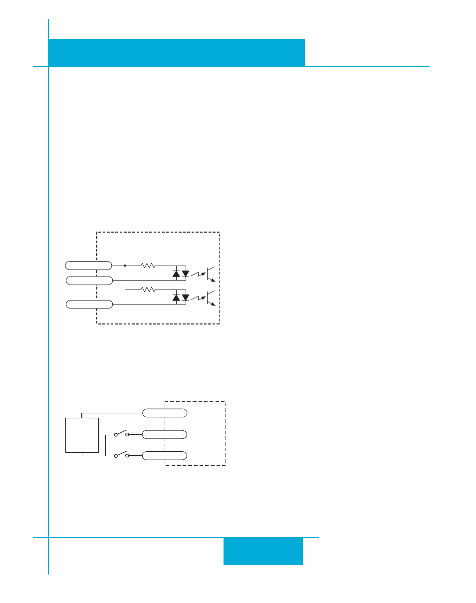
Connecting Limit switches to the STAC6 Drive
The X7/CW LIMIT and X6/CCW LIMIT inputs are used for connecting end of travel sensors. These inputs
are differential, which allows you to use signals that are sinking (NPN), sourcing (PNP) or differential (line
driver). By connecting switches or sensors that are triggered by the motion of the motor or load, you can
force the motor to operate within certain limits. This is useful if a program or operator error could cause
damage to your system by traveling too far.
The limit inputs are optically isolated. This allows you to choose a voltage for your limit circuits of 12 to 24
volts DC. This also allows you to have long wires on limit sensors that may be far from the drive with less
risk of introducing noise to the drive electronics. The schematic diagram of the limit switch input circuit is
shown below.
2200
2200
inside STAC6
IN/OUT 1 Connector
8
3
4
X COM
X7/CW LMT
X6/CCW LMT
Wiring a Mechanical Limit Switch
You can use normally open or normally closed limit switches. Either way, wire them as shown here.
STAC6
Stepper
+
12-24
VDC
SUPPLY
-
X7/CW LMT
X6/CCW LMT
X COM