27 stac6 hardware manual – Applied Motion STAC6-C User Manual
Page 27
27
STAC6 Hardware manual
920-0029 Rev. C
5/2/2012
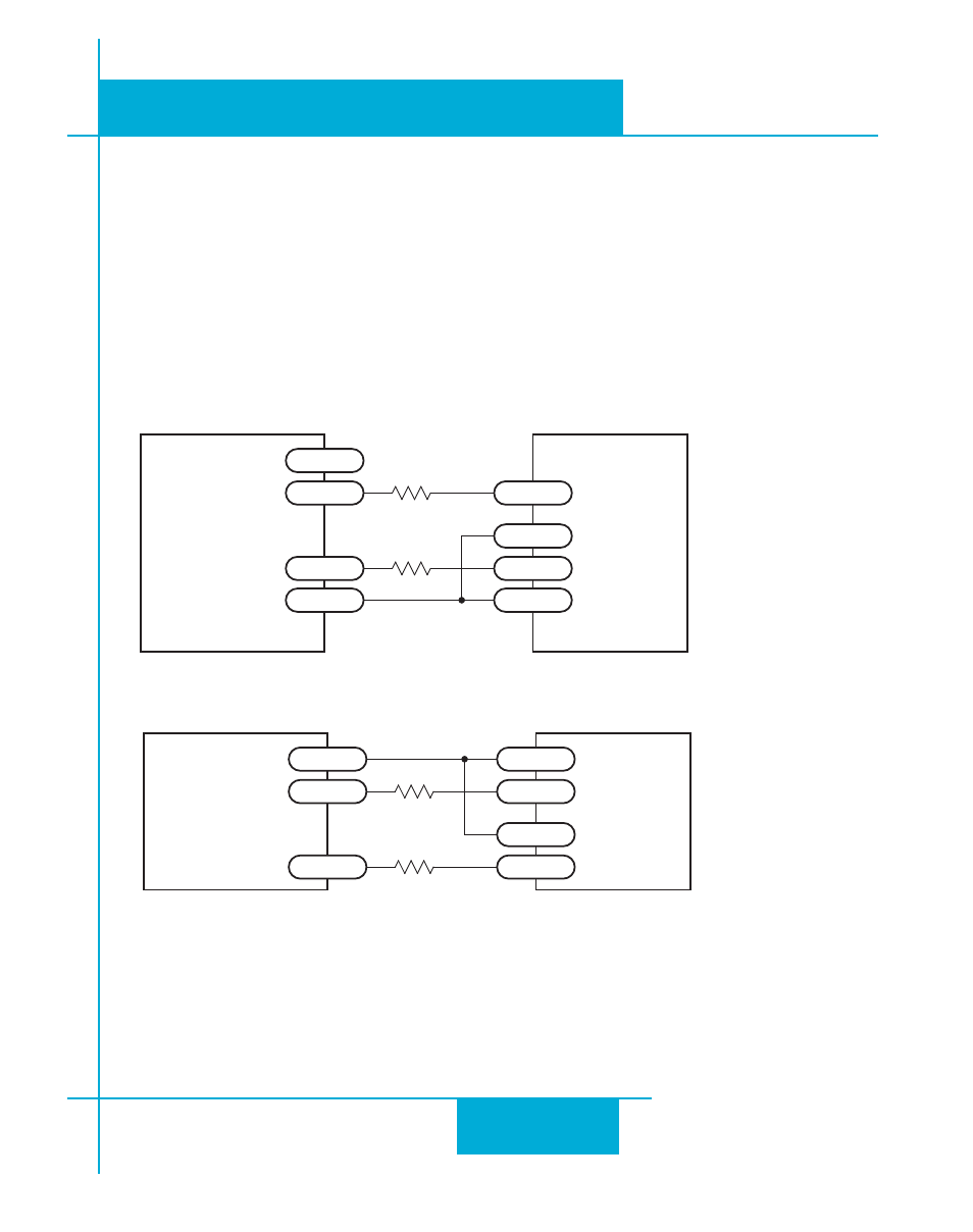
Using High Speed Inputs with 12-24 Volt Signals
Most PLCs don’t use 5 volt logic. You can connect signal levels as high as 24 volts to the STEP and DIR
inputs if you add external dropping resistors, as shown below.
For 12 volt logic, add 820 ohm, 1/4 watt resistors
For 24 volt logic, use 2200 ohm, 1/4 watt resistors
WARNING: The maximum voltage that can be applied directly to a high speed input terminal
is 24 volts. Never apply high voltage AC to an input terminal.
STAC 6
Drive
+12-24V
GND
DIR-
OUT1
DIR+
STEP-
OUT2
STEP+
PLC
with
Sourcing
Outputs
R
R
Connecting to PLC with Sourcing (PNP) Outputs (Most PLC’s use 24 volt logic)
STAC6
Drive
+12-24V
DIR+
DIR
DIR-
STEP+
STEP
STEP-
PLC
with
Sinking
Outputs
R
R
Connecting to PLC with Sinking (NPN) Outputs (Most PLC’s use 24 volt logic)