Sw2-1, Sw2-2 – Altera Signal Integrity Development Kit, Stratix V GX Edition User Manual
Page 15
Chapter 4: Development Board Setup
4–3
Factory Default Switch Settings
July 2012
Altera Corporation
Transceiver Signal Integrity Development Kit
Stratix V GX Edition User Guide
2. For power sequencing, set DIP switch bank (SW3) to match
. (For the other power sequence settings, see
.)
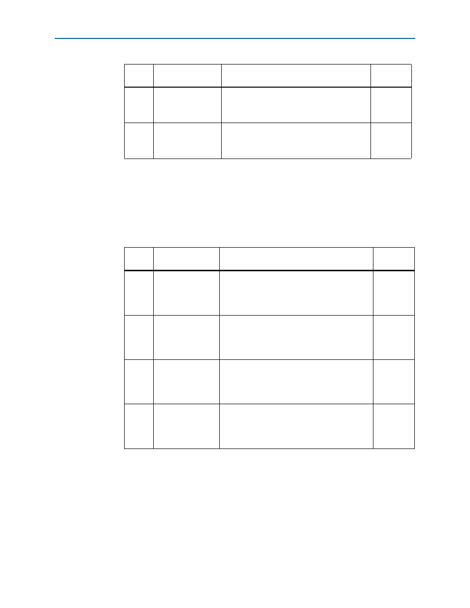
3
SW2-3
Switch 3 has the following options:
■
Open = No function
■
Closed = No function
—
4
SW2-4
Switch 4 has the following options:
■
Open = No function
■
Closed = No function
—
(1) If the board is powered off and powered on again with SW2-1 and -2 in the open position, the voltage rails
VCCRT_GXB and VCCA_GXB will not come up to their proper levels. To ensure that the voltage rails VCCRT_GXB
and VCCA_GXB come up to their proper levels, set SW2-1 and -2 to the default closed position at power up. Once
the board has power, change the rail voltages as you prefer.
Table 4–2. SW3 Dip Switch Settings
Switch
Board
Label
Function
Default
Position
1
SW3-1 VCC
Switch 1 has the following power sequencing
options:
■
S5GX_VCC is enabled.
■
S5GX_VCC is disabled.
ENABLED
2
SW3-2 VCCRT_GXB
Switch 2 has the following power sequencing
options:
■
VCCRT_GXB is enabled.
■
VCCRT_GXB is disabled.
ENABLED
3
SW3-3 VCCA_GXB
Switch 3 has the following power sequencing
options:
■
VCCA_GXB is enabled.
■
VCCA_GXB is disabled.
ENABLED
4
SW3-4 1p5V
Switch 4 has the following power sequencing
options:
■
1p5V is enabled.
■
1p5V is disabled.
ENABLED
Table 4–1. SW2 Dip Switch Settings (Part 2 of 2)
Switch
Board
Label
Function
Default
Position