Factory default switch settings, Factory default switch settings –2, Figure 4–1 – Altera Signal Integrity Development Kit, Stratix V GX Edition User Manual
Page 14: Shows the, Switch 1 has the following options, Open = vccrt_gxb select at 0.90 v, Switch 2 has the following options, Open = vcca_gxb select at 2.5 v, Close = vcca_gxb select at 3.0 v close
4–2
Chapter 4: Development Board Setup
Factory Default Switch Settings
Transceiver Signal Integrity Development Kit
July 2012
Altera Corporation
Stratix V GX Edition User Guide
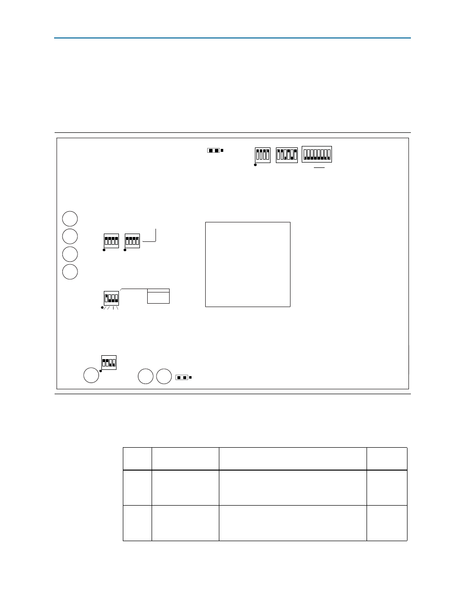
Factory Default Switch Settings
This section shows the factory switch settings for the Stratix V GX transceiver signal
integrity development board.
shows the switch locations and the default position of each switch on the
top side of the board.
To restore the switches to their factory default settings, perform the following steps:
1. Set the DIP switch bank (SW2) to match
and
.
Figure 4–1. Switch Locations and Default Settings on the Board Top
SW4
1 2 3 4 5 6 7 8
S7
1 2 3 4 5 6
MSEL0
MSEL1
MSEL2
MSEL3
MSEL4
MAX BYPASS
1
SW6
1 2 3 4
0
1
0
OSC
SMA
S5_UNLOCK
DPI6
DPI0
SW3
1 2 3 4
1 2 3 4
SW7
ENABLE
DISABLE
SW3-1 VCC
SW3-2 VCCRT_GXB
SW3-3 VCCA_GXB
SW3-4 1p5V
SW7-1 2p5V
SW7-2 VCCR_GTB
SW7-3 VCCT_GTB
SW7-4 VCCL_GTB
SW5
1 2 3 4
ON
S0 S1 SS0 SS1
S1 S0 CLK
0 0 25MHz
0 1 100MHz
1 0 125MHz
1 1 200MHz
SW2
1 2 3 4
ON
open
close
SW2-1 OPEN=0.90V
SW2-1 CLOSED=1.0V
SW2-2 OPEN=2.5V
SW2-2 CLOSED=3.0V
SW2-3 = No Function
SW2-4 = No Function
J28
(PGMSEL)
PGMSEL
JMP1-2=USER
JMP2-3=FACTORY
3
1
ON
ON
1
0
J26
AUTO ON
3
1
(Fan select)
(User defined)
0 = Closed
1 = Open
Table 4–1. SW2 Dip Switch Settings (Part 1 of 2)
Switch
Board
Label
Function
Default
Position
1
Switch 1 has the following options:
■
Open = VCCRT_GXB select at 0.90 V
■
Close = VCCRT_GXB select at 1.0 V
Close
2
Switch 2 has the following options:
■
Open = VCCA_GXB select at 2.5 V
■
Close = VCCA_GXB select at 3.0 V
Close