Altera PowerPlay Early Power Estimator User Manual
Page 34
3–16
Altera
Corporation
PowerPlay Early Power Estimator For Stratix II, Stratix II GX & HardCopy II
January 2007
PowerPlay Early Power Estimator Inputs
Each row in the DSP section represents a DSP design module where all
instances of the module have the same configuration, clock frequency,
toggle percentage and register usage. If some (or all) DSP or multiplier
instances have different configurations, you need to enter the information
in different rows. You must enter the following information for each DSP
or multiplier module:
■
Configuration
■
Clock frequency (f
MAX
) in MHz
■
Number of instances
■
Toggle percentage of the data outputs
■
Whether or not the inputs and outputs are registered
■
Whether or not the module is pipelined
f
For more information on Stratix II DSP block configurations, refer to the
DSP Blocks in Stratix II Devices chapter in volume 2 of the Stratix II Device
Handbook. For more information on Stratix II GX and HardCopy II DSP
block configurations, refer to the DSP section in the respective device
handbook.
Table 3–4
describes the values that need to be entered in the DSP section
of the PowerPlay Early Power Estimator.
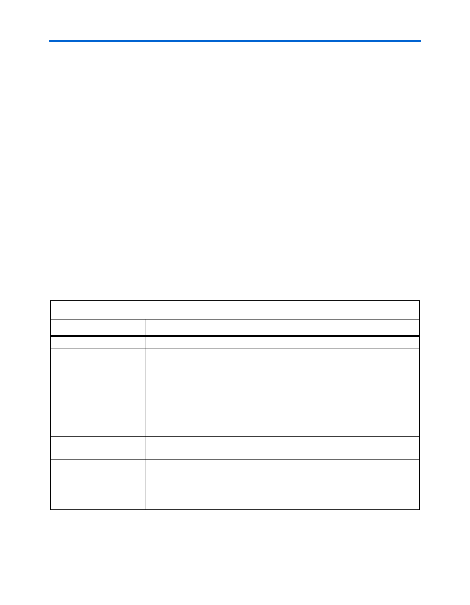
Table 3–4. DSP & Multiplier Section Information (Part 1 of 2)
Column Heading
Description
Module
Enter a name for the DSP module in this column. This is an optional value.
Configuration
Select the DSP block configuration. The following configurations are offered:
●
9 × 9 simple multiplier
●
18 × 18 simple multiplier
●
36 × 36 simple multiplier
●
18 × 18 multiplier-accumulator
●
9 × 9 two-multiplier-adder
●
18 × 18 two-multiplier-adder
●
9 × 9 four-multiplier-adder
●
18 × 18 four-multiplier-adder
Clock Freq
Enter the clock frequency for the module in MHz. This value is limited by the
maximum frequency specification for the device family.
# of Instances
Enter the number of instances that have the same configuration, clock frequency,
toggle percentage and register usage. This value is independent of the number of
dedicated DSP blocks being used. For example, it is possible to use four
9 × 9 simple multipliers that would all be implemented in the same DSP block in a
Stratix II device. In this case, the number of instances would be four.