Pilz PDP20 F 4 mag User Manual
Page 4
- 4 -
Verdrahtung
1410359307
Beachten Sie:
Angaben im Abschnitt "Technische Daten"
unbedingt einhalten.
Berechnung der max. Leitungslänge I
max
im
Eingangskreis:
R
lmax
= max. Gesamtleitungswiderstand
(s. techn. Daten des Auswertegeräts)
Ri = Innenwiderstand Sensor (s. techn. Da-
ten Sensor)
R
l
/ km = Leitungswiderstand/km des Ka-
bels (s. techn. Daten Kabelhersteller)
Das Netzteil muss den Vorschriften für Klein-
spannungen mit sicherer Trennung (SELV,
PELV) entsprechen.
Pro Klemme darf 1 Draht verdrahtet werden.
Verwenden Sie eine Reihenklemme, wenn
mehrere Anschlüsse pro Klemme notwendig
sind.
Leitungsmaterial aus Kupferdraht mit einer
Temperaturbeständigkeit von 60/75 °C ver-
wenden.
Wiring
Please note:
Information given in the "Technical details"
must be followed.
Calculation of the max. cable length l
max
in
the input circuit:
R
lmax
= Max. overall cable resistance (see
evaluation device's techn. details)
Ri = Internal sensor resistance (see sensor's
techn. details)
R
l
/ km = Cable resistance/km (see cable
manufacturer's techn. details)
The power supply must meet the regulations
for extra low voltages with safe separation
(SELV, PELV).
1 wire may be connected per terminal. Use a
terminal block if you need multiple connec-
tions per terminal.
Use copper wire that can withstand 60/
75 °C.
Raccordement
Important :
Respecter impérativement les données indi-
quées dans le paragraphe « Caractéristiques
techniques ».
Calcul de la longueur de câble max. I
max
sur
le circuit d'entrée :
R
lmax
= résistance max. de l'ensemble du
câblage (voir les caractéristiques techni-
ques de l'unité de contrôle)
Ri = résistance interne du capteur (voir ca-
ractéristiques techniques du capteur)
R
l
/ km = résistance du câble/km (voir ca-
ractéristiques techniques du fabricant du
câble)
Cette alimentation doit être conforme aux
prescriptions relatives aux basses tensions à
séparation galvanique (SELV, PELV).
On ne peut câbler qu'un fil par borne. Utilisez
un bornier sur rail si plusieurs raccordements
sont nécessaires par borne.
Utilisez uniquement des fils de câblage en
cuivre résistant à des températures de 60/
75 °C.
Zulässige Sensoren von Pilz
1421088651
PSENmag:
– PSEN 1.1p-10, PSEN 1.1p-20
– PSEN ma1.3-20 M12, PSEN ma1.3a-20,
PSEN ma1.3b-20, PSEN ma1.3b-23,
PSEN ma1.3n-20, PSEN ma1.3p-20
– PSEN ma1.4-51 M12, PSEN ma1.4a-50,
PSEN ma1.4a-51, PSEN ma1.4n-50,
PSEN ma1.4n-51, PSEN ma1.4p-50,
PSEN ma1.4p-51
PSENhinge
– PSEN hs1.1p
– PSEN hs1.2p
PSENrope
– PSEN rs1.0
– PSEN rs2.0
PITestop
– PIT es Set1s-5, PIT es Set1s-5c, PIT es
Set1s-5ns
– PIT esc1, PIT esc1c, PIT esc2, PIT esc2c
Permitted sensors from Pilz
PSENmag:
– PSEN 1.1p-10, PSEN 1.1p-20
– PSEN ma1.3-20 M12, PSEN ma1.3a-20,
PSEN ma1.3b-20, PSEN ma1.3b-23,
PSEN ma1.3n-20, PSEN ma1.3p-20
– PSEN ma1.4-51 M12, PSEN ma1.4a-50,
PSEN ma1.4a-51, PSEN ma1.4n-50,
PSEN ma1.4n-51, PSEN ma1.4p-50,
PSEN ma1.4p-51
PSENhinge
– PSEN hs1.1p
– PSEN hs1.2p
PSENrope
– PSEN rs1.0
– PSEN rs2.0
PITestop
– PIT es Set1s-5, PIT es Set1s-5c, PIT es
Set1s-5ns
– PIT esc1, PIT esc1c, PIT esc2, PIT esc2c
Capteurs autorisés de Pilz
PSENmag:
– PSEN 1.1p-10, PSEN 1.1p-20
– PSEN ma1.3-20 M12, PSEN ma1.3a-20,
PSEN ma1.3b-20, PSEN ma1.3b-23,
PSEN ma1.3n-20, PSEN ma1.3p-20
– PSEN ma1.4-51 M12, PSEN ma1.4a-50,
PSEN ma1.4a-51, PSEN ma1.4n-50,
PSEN ma1.4n-51, PSEN ma1.4p-50,
PSEN ma1.4p-51
PSENhinge
– PSEN hs1.1p
– PSEN hs1.2p
PSENrope
– PSEN rs1.0
– PSEN rs2.0
PITestop
– PIT es Set1s-5, PIT es Set1s-5c, PIT es
Set1s-5ns
– PIT esc1, PIT esc1c, PIT esc2, PIT esc2c
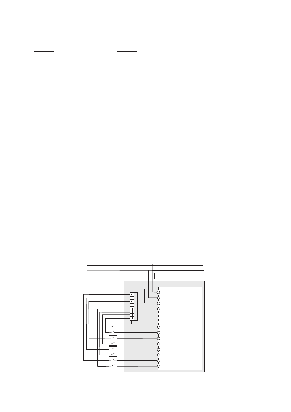
Betriebsbereitschaft herstellen
1408976779
Einzelschaltung
X1: Reihenklemme
grauer Bereich: Schaltschrank
Preparing for operation
Single connection
X1: Terminal block
Grey area: Control cabinet
Préparation à la mise en service
Montage simple
X1 : bornier
Zone grise : armoire électrique
R
lmax
- R
i
R
l
/ km
I
max
=
R
lmax
- R
i
R
l
/ km
I
max
=
R
lmax
- R
i
R
l
/ km
I
max
=
T0
PDP20 F 4 mag
T1
I10
I31
I30
I21
I20
I11
I41
I40
A1
A2
24 V
0 V
X1
T0
T0
T0
T0
T1
T1
T1
T1
F1