Pilz PDP20 F 4 mag User Manual
Page 3
- 3 -
1443007499
Zeitdiagramm
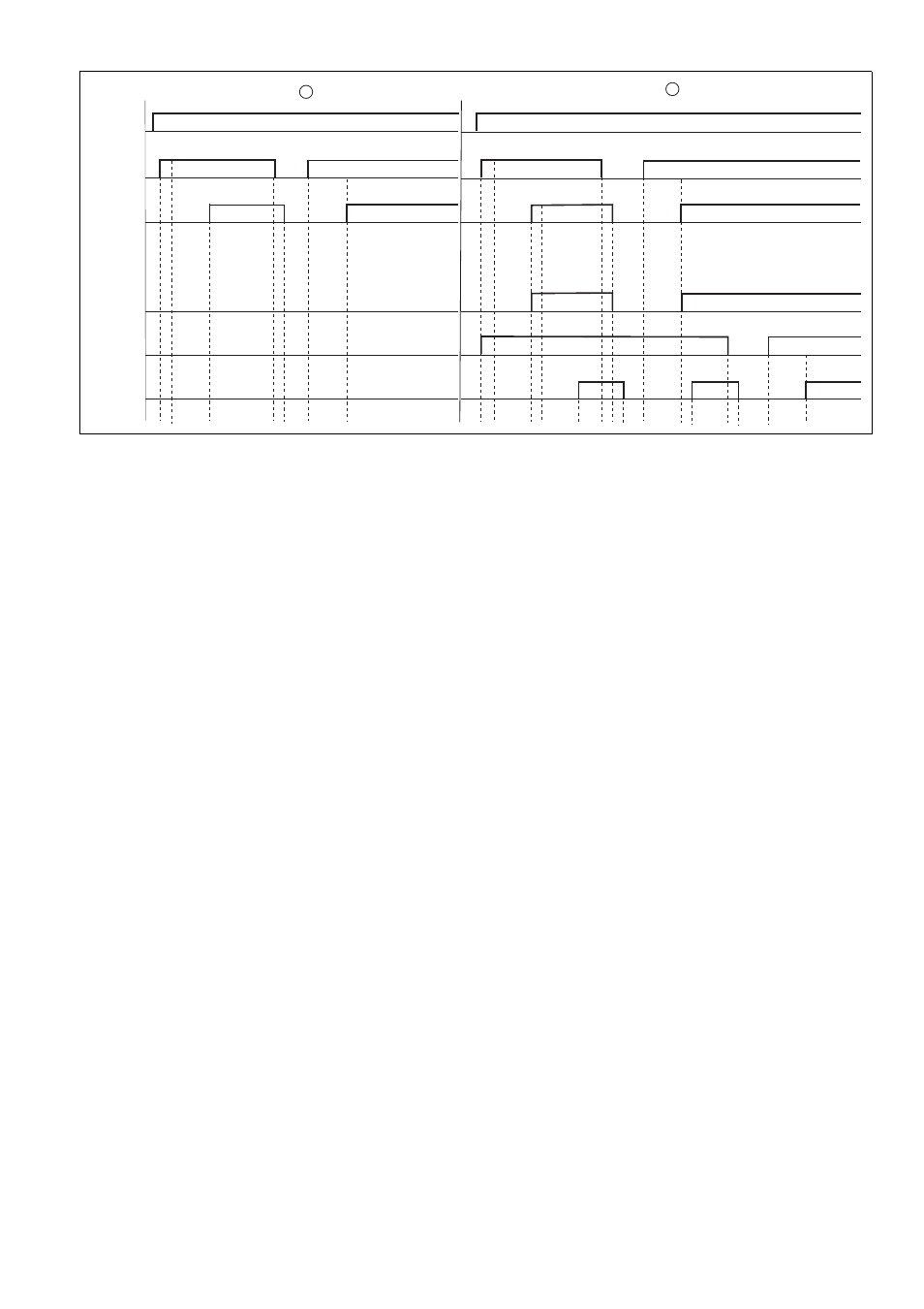
Timing diagram
Diagramme temporel
1442984715
Legende
: Einzelschaltung mit Gerät Unit 1
: Reihenschaltung von Gerät Unit 1 und
Unit 2
Power: Versorgungsspannung
Unit 1, I10 ... I41: Eingangskreise des Geräts
Unit 1
Unit 1, O0/O1: Sicherheitsausgänge des Ge-
räts Unit 1
Unit 2, I40- I41: Kaskadiereingang des Ge-
räts Unit 2
Unit 2, I10 ... I31: Eingangskreise des Geräts
Unit 2
Unit 2, O0/O1: Sicherheitsausgänge des Ge-
räts Unit 2
t
1
: max. Verarbeitungszeit des Eingangs bei
Signalwechsel von "0" nach "1"
t
2
: typ. Einschaltverzögerung
t
3
: max. Verarbeitungszeit des Halbleiteraus-
gangs bei Signalwechsel von "1" nach "0"
Key
: Single connection with Unit 1
: Series connection from Unit 1 and Unit 2
Power: Supply voltage
Unit 1, I10 ... I41: Input circuits of Unit 1
Unit 1, O0/O1: Safety outputs of Unit 1
Unit 2, I40- I41: Cascading input of Unit 2
Unit 2, I10 ... I31: Input circuits of Unit 2
Unit 2, O0/O1: Safety outputs of Unit 2
t
1
: Max. processing time for input when sig-
nal changes from "0" to "1"
t
2
: Typ. switch-on delay
t
3
: Max. processing time for semiconductor
output when signal changes from "1" to "0"
Légende
: montage simple avec l'appareil Unit 1
: montage en série des appareils Unit 1 et
Unit 2
Power : tension d'alimentation
Unit 1, I10 à I41 : circuits d'entrées de l'appa-
reil Unit 1
Unit 1, O0/O1 : sorties de sécurité de l'appa-
reil Unit 1
Unit 2, I40- I41 : sortie de mise en cascade
de l'appareil Unit 2
Unit 2, I10 à I31 : circuits d'entrées de l'appa-
reil Unit 2
Unit 2, O0/O1 : sorties de sécurité de l'appa-
reil Unit 2
t
1
: temps de traitement max. de l'entrée
pour un changement de signal de « 0 »
à « 1 »
t
2
: temps de montée caractéristique
t
3
: temps de traitement max. de la sortie sta-
tique pour un changement de signal de « 1 »
à « 0 »
Montage
117714315
Montieren Sie das Sicherheitsschaltgerät in
einen Schaltschrank mit einer Schutzart von
mindestens IP54.
Befestigen Sie das Gerät mithilfe des Rast-
elements auf der Rückseite auf einer Norm-
schiene.
Sichern Sie das Gerät auf einer senkrechten
Normschiene (35 mm) durch ein Halte-
element (z. B. Endhalter oder Endwinkel).
Installation
The safety relay should be installed in a con-
trol cabinet with a protection type of at least
IP54.
Use the notch on the rear of the unit to attach
it to a DIN rail.
Ensure the unit is mounted securely on a ver-
tical DIN rail (35 mm) by using a fixing ele-
ment (e.g. retaining bracket or an end angle).
Montage
Montez le bloc logique de sécurité dans une
armoire électrique ayant un indice de protec-
tion d'au moins IP54.
Montez l'appareil sur un rail DIN à l'aide du
système de fixation situé sur la face arrière.
Fixez l'appareil monté sur un rail DIN vertical
(35 mm) à l'aide d'un élément de maintien
(par exemple : un support terminal ou une
équerre terminale).
POWER
t
2
Unit 1
I10...I41
Unit 1
O0/O1
Unit 2
I40-I41
Unit 2
I10...I31
Unit 2
O0/O1
t
2
t
3
t
2
t
3
t
3
t
2
t
2
t
1
t
1
t
3
1
2
t
1
t
2
t
1