3 series connection of modules, 4 examples of series connection, 6wiring – Pilz PDP67 F 4 code User Manual
Page 23: 3 preparing for operation
Pilz GmbH & Co. KG, Felix-Wankel-Straße 2, 73760 Ostfildern, Germany
Telephone: +49 711 3409-0, Telefax: +49 711 3409-133, E-Mail: [email protected]
6-7
6.3
Preparing for operation
6
Wiring
6.3.1.3
Series connection of modules
Series connection of modules
6-
Anschluss_PDP_PSEN_Reihenschaltung_Info
Please note:
The series connection of the modules is always created with the last
free female connector X2 ... . X5 and the X1 female connector of the
next module. The adapter
PDP67 Connector cs/PDP67 Connector
cs VA must be used for connecting the modules in series.
The voltage at the last module must not fall below the permitted sup-
ply voltage level. Please refer to the operating manual for the sensors
used for the permissible values for the supply voltage (see "Voltage
tolerance" in the chapter entitled "Technical details"). An example of
how the voltage drop is calculated can be found in the chapter enti-
tled "Voltage drop".
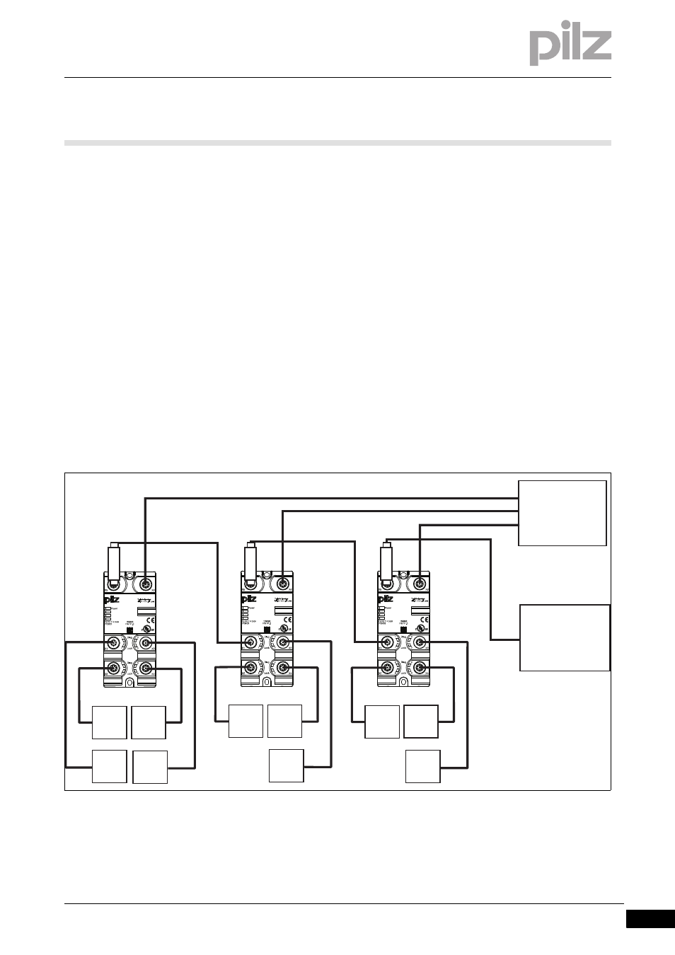
6.3.1.4
Examples of series connection
Examples of series connection
6-
Anschluss_PDP_PSEN_Reihenschaltung_4_Sensoren
Connection example 1: Series connection for connecting four sensors
(X1 ... X4) to the first module
*Adapter:
PDP67 Connector cs/PDP67 Connector cs VA
Anschluss_PDP_PSEN_Reihenschaltung_3_Sensoren
*
*
FS: Fail-Safe
ST
ST
ST
FS
Adapter
Adapter
Adapter
Evaluation device
PLC
ST: Standard
*
PSEN PSEN
PSEN
PSEN PSEN
PSEN PSEN
PSEN
PSEN
PSEN