4 function description, 1 module features, 1 functions – Pilz PSSu E F 2DI 60-R User Manual
Page 12: 2 integrated protection mechanisms, Section 4, Function description, Module features, Functions, Integrated protection mechanisms, 4function description
Function description
Operating Manual PSSu E F 2DI 60R
1002506EN02
12
4
Function description
4.1
Module features
4.1.1
Functions
Module supply
}
The module supply provides the module with voltage.
Inputs
}
The status of the inputs is signalled to the head module via the module bus.
}
The module's inputs are galvanically isolated from each other and from the module sup
ply.
}
The inputs have input filters.
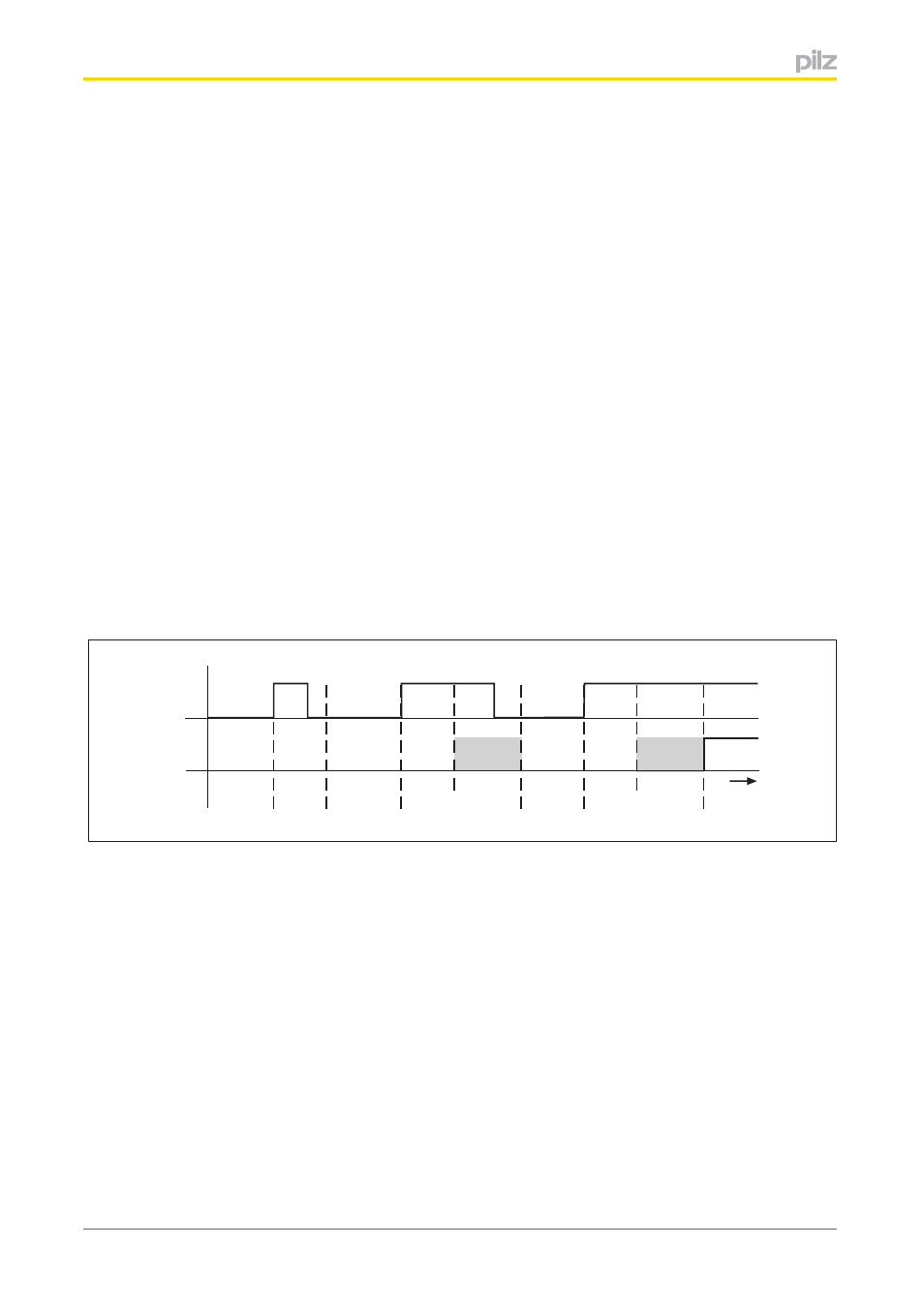
Signal detection at the inputs
}
A signal (“0” signal or “1” signal) is always ignored if it is present for less than the min
imum processing time (see Technical details).
}
A signal is always detected and transmitted to the process image (PII) if it is present for
longer than the maximum processing time plus the scan time of the module bus (t
2
+ t
3
,
see diagram and Technical details).
Timing diagram
Input
PII
t
2
+t
3
t
t
1
t
1
t
2
+t
3
t
1
}
Input: Signal at the input
}
PII: Status of process image (PII)
}
t
1
Minimum processing time (see Technical details)
}
t
2
Maximum processing time (see Technical details)
}
t
3
Cycle time of module bus
Shaded area: Status of process image (PII) undefined.
4.1.2
Integrated protection mechanisms
When the PSSu E F PS1(T) is used to supply the system, the module supply is buffered
for 20 ms if the supply voltage is interrupted.
The module provides the following diagnostic data:
}
Startup error
}
Configuration error