6 wiring, 1 general wiring guidelines, 1 mechanical connection of the base modules – Pilz PSSu E F 2DO 2 User Manual
Page 23: Section 6, Wiring, General wiring guidelines, Mechanical connection of the base modules, 6wiring, Din 5264-a
Wiring
Operating Manual PSSu E F 2DO 2(T)(R)
21322EN05
23
6
Wiring
6.1
General wiring guidelines
Please note:
}
If short circuits occur between the cable from the output to the load and a supply line, it
will no longer be possible to switch off the load. Possible remedies:
}
Use separate multicore cable for supply voltages
–
Use dual actuators, e.g. two contactors in series
–
Use an additional shutdown device such as a main contactor
}
Use appropriate wiring to exclude short circuits between the outputs!
}
With singlechannel operation for applications up to Category 3 in accordance with EN
9541: use a feedback loop!
}
When used for Category 4 applications in accordance with EN 9541: connect two actu
ators connected in series to two different outputs!
}
The actuators may be connected using unshielded cables.
}
The outputs do not need suppression for inductive loads.
}
Use copper wiring.
}
The terminal configuration as stated on the front plate applies for base modules with C
rail. The terminal configuration as stated in the technical documentation applies for all
other base modules.
6.1.1
Mechanical connection of the base modules
Procedure:
}
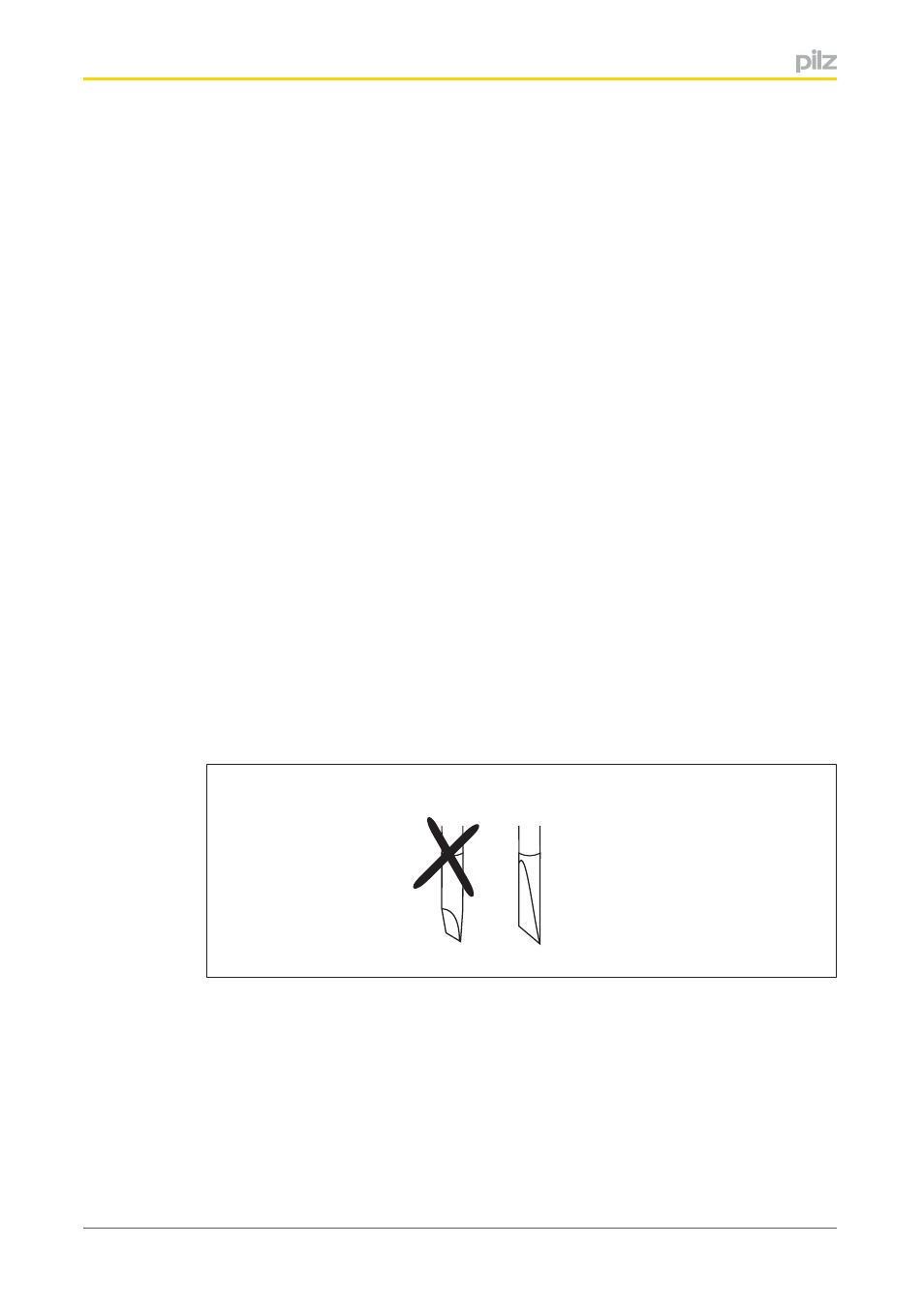
Use a flat blade screwdriver (DIN 5264A)!
DIN 5264-A
}
Strip the wire back 8 mm.
}
If necessary, label the connection level with a colour marker [3].
}
Base module with screw terminals:
–
Use a screwdriver to loosen the screw on the screw terminal [1]
–
Insert the stripped cable into the round fixing hole [2], as far as it will go.
–
Tighten up the screw on the screw terminal.
–
Check that the cable is firmly seated.