Interfaces, Interface configuration, Connection to profibus dp – Pilz PSSu H DP User Manual
Page 21: 6interfaces, 1 interface configuration, 1 connection to profibus dp
Pilz GmbH & Co. KG, Felix-Wankel-Straße 2, 73760 Ostfildern, Germany
Telephone: +49 711 3409-0, Telefax: +49 711 3409-133, E-Mail: [email protected]
6-1
6.1
Interface configuration
6
Interfaces
6
6000
Interfaces
Interfaces
6-
6.1
Interface configuration
6100
Interface configuration
6-
][Anschluss DP + USB
n.c. = not connected
6.1.1
Connection to PROFIBUS DP
Connection to PROFIBUS DP
6-
][BA_Verdrahtung DP
The PSSu is connected to PROFIBUS DP via RS 485 communication.
The PSSu supplies the PROFIBUS DP bus terminating resistors with
voltage (+5 VDC).
Connect the connector housing to the screening on the PROFIBUS
cable. The connector housing should be connected with low imped-
ance to the mounting rail.
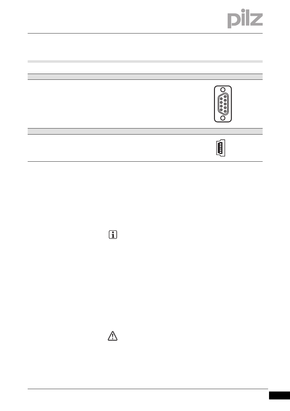
PROFIBUS DP
Layout
Female 9-pin D-SUB connector con-
forms to the guidelines of the PROFI-
BUS User Group (PNO)
1: n.c.
2: n.c.
3: RxD/TxD-P (B-line)
4: CNTR-P (RTS)
5: DGND (GND ext.)
6: VP (+5 V ext.)
7: n.c.
8: RxD/TxD-N (A-line)
9: n.c.
USB
Layout
Mini-B USB connector
1: n.c.
2: D- USB Data –
3: D+ USB Data +
4: n.c.
5: GND Ground
INFORMATION
The two data lines are also called A and B on PROFIBUS.
Always connect the A-line (“RxD/TxD-N”) to the A-lines of all the
other PROFIBUS subscribers.
The B-line (“RxD/TxD-P”) should only be connected to the B-
lines of the other PROFIBUS subscribers.
If communication is not established, check the connections
using a continuity tester.
CAUTION!
Do not use the signals VP (+5 V ext.) and DGND (GND ext.) to
supply voltage to external devices! They are exclusively used to
supply the PROFIBUS DP bus terminating resistors.
1
5
9
6
1
5