Installation, Wiring, Preparing for operation – Pilz PNOZ c2 24VDC 2n/o User Manual
Page 7
PNOZ c2
Operating Manual PNOZ c2
22212EN02
7
Installation
}
The unit should be installed in a control cabinet with a protection type of at least IP54.
}
Use the notch on the rear of the unit to attach it to a DIN rail.
}
Ensure the unit is mounted securely on a vertical DIN rail (35 mm) by using a fixing ele
ment (e.g. retaining bracket or an end angle).
Wiring
Please note:
}
Information given in the "Technical details" must be followed.
}
Outputs 1314 and 2324 are safety contacts, the semiconductor output Y32 is an auxil
iary output (e.g. for display).
}
Semiconductor output Y32 should not be used for safety circuits!
}
To prevent contact welding, a fuse should be connected before the output contacts (see
Technical details).
}
Use copper wire that can withstand 60/75 °C.
}
Do not connect capacitive load.
}
The power supply must comply with the regulations for extra low voltages with protect
ive electrical separation (SELV, PELV) in accordance with VDE 0100, Part 410.
INFORMATION
The voltage at the inputs S12, S22 has to be at least 24 V DC less the lower
tolerance value of the supply voltage (s. technical details). When the voltage
is too low, increase the supply voltage until at least the lower tolerance
value is reached at the inputs.
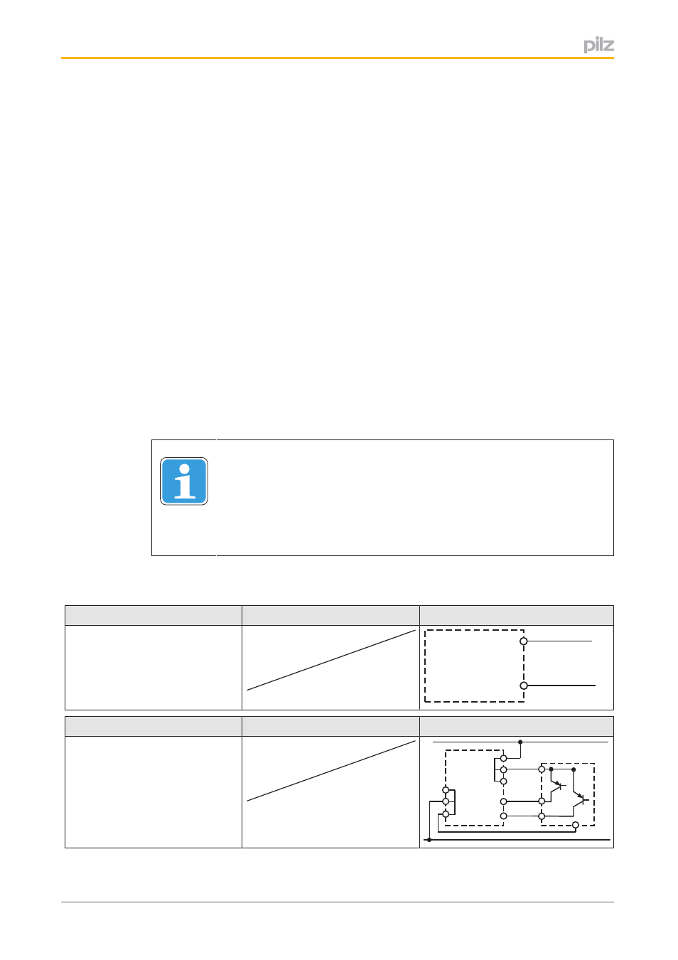
Preparing for operation
Supply voltage
AC
DC
A1
L+
A2
L-
Input circuit
Singlechannel
Dualchannel
Light guard or safe sensor with
detection of shorts across con
tacts and short circuit proof
OSSDs
A1
A1
A1
A2
A2
A2
S12
S22
24 V DC
GND
*
*