Stealth power head, Pparrtss iddentiffiicaatiioon, Combined parts list – Genie Pro max PMX-IC B Series User Manual
Page 6
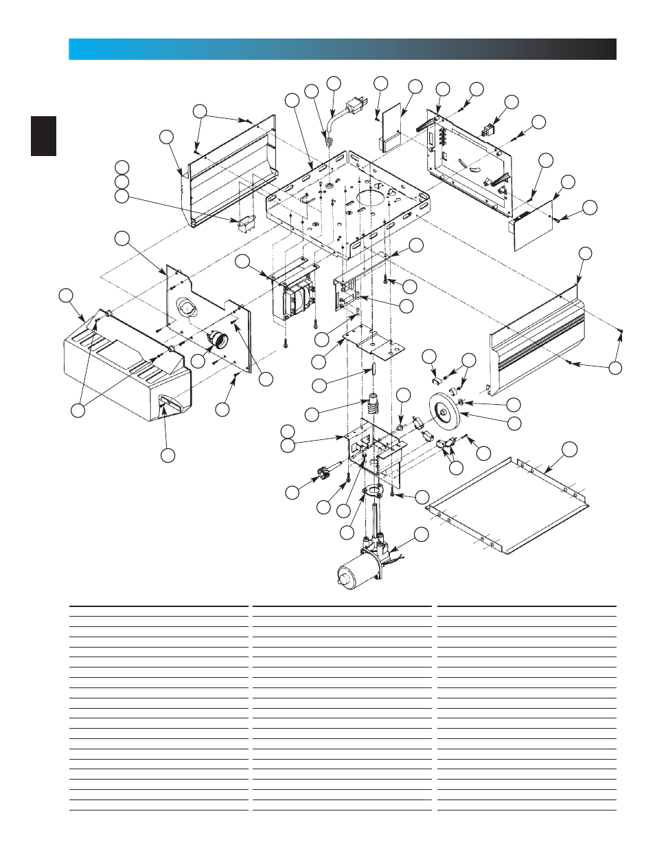
Stealth Power Head
2
3
4
5
6
7
8
9
10
1
12
13
14
15
16
17
18
19
20
11
22
23
24
25
26
27
28
29
30
21
32
33
34
35
36
37
38
39
31
40
12
12
12
12
11
19
3
12
26
26
Item Part Name
1 Lens
2 Front Cover
3 Side Cover (by series/model)
4 Top Plate Assembly
5 Strain Relief
6 Cord & Plug Assembly
7 Component Panel (by series/model)
8 Bottom Cover
9 Screw, #8 x .75 Phil Hx Hd/W Sf Tap
10 Screw, #8 x .62 Phil Pan Hd/W Sf Tap
11 Screw, #8 x .50 Slt Hx Hd/W Sf Tap
12 Screw, #8 x .38 Slt Hx Hd/W Sf Tap
13 Light Socket (by series/model)
14 Terminal Block & Lug
15 M.O.V. Assembly
16 Receiver Assembly
17 Limit Set Switch
18 Sequencer Assembly
19 Screw, #6 x .38 Slt Hx Hd/W Sf Tap
20 Transformer Assembly (by series/model)
6
PPARRTSS IDDENTIFFIICAATIIOON
FORR HEELP-1..88000.3544.33643 ORR GENNIIECOMMPPAANNY..COMM
Item Part Name
21 Rectifier Board Assembly
22 Fuse (F1), UL
23 Fuse (F2), UL
24 Limit Gear Shroud
25 Motor Bracket
26 Screw, #10 x 3/8
”
HH
27 Limit Plate/Pin Assembly
28 Limit Switch
29 Screw,#4 40x5/8
”
SlotHHw/Wshr,SfTap
30 Motor Assembly
31 Motor Adapter Plate
32 Screw, 1/4"-20 x 1/2
”
Slt HH w/Wshr
33 Limit Worm Gear
34 Limit Gear Bushing
35 Limit Worm Drive
36 Limit Worm Shim
37 Limit Wheel
38 Retaining Ring
39 Limit Cam
40 Limit Pinion, 8 tooth
Item Part Name
41 Capacitor
42 Capacitor Clamp
43 Screw, #10-24 x 1/2
”
, Slot HH Sf-Tap
44 Nut, #10-32, Hex Serrated Flange
45 Circuit Board
46 C.B. Bracket
47 Circuit Board Mount
48 Screw, #10-16 x 5/8
”
, HH Sf Tap
49 Top Gear Housing
50 Middle Gear Housing
51 Bottom Gear Housing
52 Drive Shaft Bushing
53 Drive Thrust Washer
54 Drive Shaft
55 1/2
”
Retaining Ring
56 Main Drive Worm Gear
57 Optical Interrupt Wheel
58 Motor Flanged Bushing
59 Motor Thrust Washer
60 Poly Thrust Washer
Combined Parts List