Open red parts bag, Warning, Ssafe--tt--bbeeaamm – Genie Pro max PMX-IC B Series User Manual
Page 18: Iinnsstaalllaattionn, Fig. 3-4), Fig. 3-3), Fig.3-5), Fig. 3-1), Fig. 3-2), E-t-beam
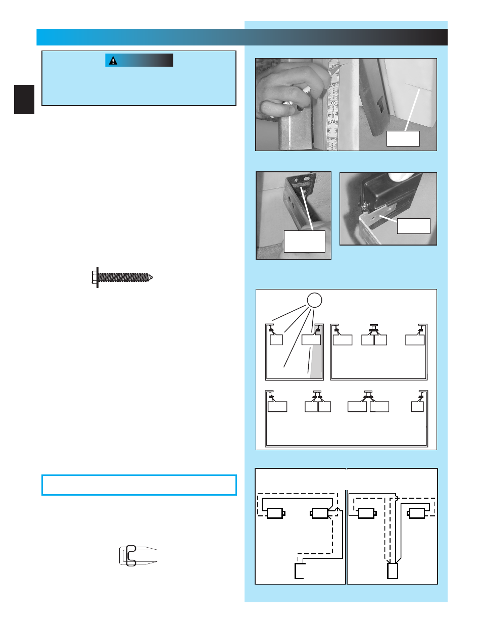
NOTE: Mountiing bracckettss caan be attttaachedd ttoo tthhee
floor usiing cooncrete aanchors (nnoott pprroovvidedd))..
2. Mounting STB source and sensor
.
•
If garage has only one garage door.
–
Determine which side of garage receives
most direct sunlight
(Fig. 3-4)
.
–
Red LED should always be on sunny side
whenever possible
(Fig. 3-4)
.
•
For multiple doors.
–
Preventing crossed signals is critical.
–
Place source and sensor modules on
adjacent doors facing in opposite directions
(Fig. 3-4)
.
NOTE::Too hellppreevenntinnterrffereencefroom sun, SSTBB
sennssorrs((ggreeen LEED)) mayy bee plaaced ffuurrtherr awwayy
from tthhe ddoooor opening wwherre tthheey willl sspennd morree
timme iin shhadoowws..
•
Slide source/sensor onto tongue of bracket
until it clicks into place
(Fig. 3-3)
.
3.
.
•
Routewire using either method shown
(Fig.3-5)
.
•
Securely fasten wires to wall as you go.
–
Use insulated staples (included).
–
Staples should be snug only.
WARNING
NNNNOOTTTTEEEE::: TTTThhhheeee ooppeerrraaaattoorrr wwiilllllll nnoott cclloooossssee ttthhee dddooooooorrrr
aautomaticcalllly uunnllesss the SSaafe--T-Beaam
®
SSyystemm
iis innsstalllledd..
1.
kets
.
•
Mark both sides of garage door frame or wall 5
”
above floor
(Fig. 3-1)
.
•
Hold bracket against door frame or wall.
–
Check if brackets extend out from wall far
enough, so tongue of bracket is beyond door,
tracks or any door hardware.
–
If not:
a. STB bracket extensions are available at
local dealer.
b. Blocks of wood, etc. may be substituted
for extensions.
•
Center bracket on your mark
(Fig. 3-2)
.
•
Fasten each with 2 screws [127].
e-T-Beam
®
System
If you have plugged in the po
d
—UNPLUG IT NOW.
FIG.
.
FIG. 3-2
kets
.
F
IG. 3-3
Attaching STB
’
kets
(See directions on next page and
Figure 3-4 before attaching.)
tongue
br ket
#10-16 x 1-1/4
”
FIG.
.
Sensor
Source
Red
Green
Power
Head
Sensor
Source
Red
Green
Power
Head
A
B
Dashed Line = striped wire
Solid Line = white wire
FIG. 3-4 STB locations
.
SUN
ONE DOOR
GARAGE
THREE DOOR
GARAGE
RED
LED
RED
LED
GREEN
LED
RED
LED
GREEN
LED
GREEN
LED
GREEN
LED
RED
LED
RED
LED
RED
LED
GREEN
LED
GREEN
LED
TWO DOOR
GARAGE
18
333
...
SSAFE--TT--BBEEAAMM
®
IINNSSTAALLLAATTIONN
FOR HEELPP-1..8000.354..36643 ORR GENNIECOMMPAANNY..COMM
OPEN RED PARTS BAG
[128]
[127]
Insulated staple