Toreduce the risk of severe injury or death, Open orange parts bag, Important installation instructions – Genie Pro max PMX-IC B Series User Manual
Page 11: Iinsttallaattionn, Fasten rail to power head, X 1/2, Hex head screws [69, Tighten screws
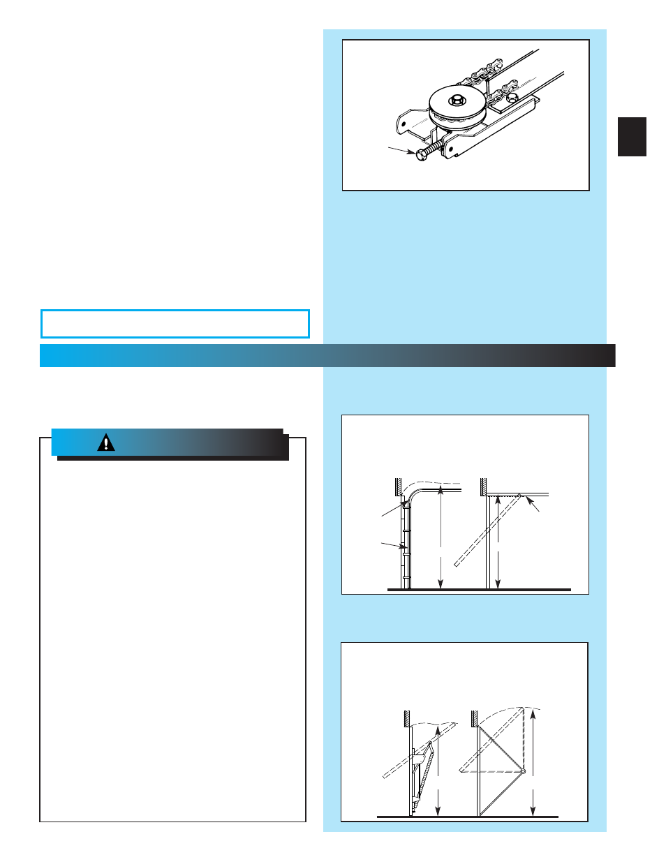
Fig. 1-4
Adjusting
Bolt
WWHHAAAATTT TTYYYPPPPEE OOOFF DDOOOOOORR DDDDOO YYOOOOUU HHAAVVVEE??
LLooooookk aatt tttthhee ddrrrraaawwwwiiinnnnggss bbeeeelllloooww.. TThheeeeyyy tttteelllllll yyyyoooouu wwhhheeerrrree
ttooo ffiinndddd tthheee iinnnnssttaallllaattiioonnnn iinnssttrrrruuuuccttiioonnnnss yyoouu nneeeedd
Track Guided Doors
SEE SECTION 2A
Trackless Doors
SEE SECTION 2
B.
Section Door With
Curved Track Hardware
1-Piece Door With
Horizontal Track Hardware
Curved
Track
with
Vertical
Section
Straight Track
(Horizontal Only)
1-Piece Door
Jamb Type Hardware
(No Track)
1-Piece Door
Pivot Type Hardware
(No Track)
5. Fasten rail to power head.
•
Align mounting holes of sprocket saddle, rail
and power head frame.
• Insert the two (2) 5/16
”
x 1/2
”
hex head
screws[112], then two (2) No. 10-24 x 1/2
”
hex
head screws [69].
•
Tighten screws.
NNOOTE: Innerr--ssliddee/bulllet shhoouulld remaiin att miidd--ttrraavel
wwhenn aasseembliing to powerr hheeadd tto pprroovvide pprrooppeer
ttrraaveel whheen settttiing limiitss.
6. Use adjusting bolt to set chain tension (Fig. 1-4)
•
Chain should sag slightly but not so much that it
drags on the rail.
“
H
”
“
H
”
“
H
”
DOTTED LINE AT
“
H
”
INDICATES HIGHEST
POINT OF TRAVEL
“
H
”
22
...
IINSTTALLAATTIONN
FOR HHEELLPP-1..8000.354..36643 OR GGENIECOMMPAANY.COMM
11
IMPORTANT
INSTALLATION
INSTRUCTIONS
1. READ AND FOLLOW ALL SAFETY, INSTALLATION AND
OPERATION INSTRUCTIONS. If you have any questions or
do not understand an instruction, call your service
representative.
2. Do Not install operator on an improperly balanced door. An
improperly balanced door could cause severe injury. Repairs
and adjustments to cables, spring assembly, and other
hardware must be made by a trained service person using
proper tools and instructions.
3. Remove all ropes and disable all locks connected to the
door before installing operator.
4. Install door operator 7 feet or more above the floor. Mount
the emergency release knob 6 feet above the floor.
5. Do Not connect the operator to the source of power until
instructed to do so.
6. Locate the control button:
• Within sight of door.
• At a minimum height of 5 feet, so small children cannot
reach it.
• Away from all moving parts of the door.
7. Install the entrapment WARNING label next to the wall
button or console. Install the emergency release tag on, or
next to, the emergency release.
8. The operator must reverse when the door contacts a 1-1/2
inch high object on the floor at the center of the doorway.
This is about the size of a 2” x 4” board laid flat.
Toreduce the risk of
severe injury or death:
WWW
WAAAARRRNNNIIINNGGGG
::::
OPEN ORANGE PARTS BAG