Caution warning, Om po ol, Remove 1/2 – Genie Pro max PMX-IC B Series User Manual
Page 20: Insulation from eac (fig. 3-6), Attac 4-1a) (max fig. 4-1b), Mount wall control (fig. 4-2), Po d must be unplugged befor hing h each other or, Use of an ol will cause the light not to wor, Place the wall control, Away from moving parts of door and door hardware
CAUTION
WARNING
Wall console
Wall button
OR
Fig. 4-2
#6 x 1-1/4
”
ws
Fig. 4-3
MORE
MENT
OPEN
PUSH
L MITS
TO SET
G4
Y3
2
W1
1.
om po
ol.
•
Place the wall control:
–
In sight of door.
–
At least 5 feet from floor, so small children can
not reach it.
–
Away from moving parts of door and
door hardware.
•
Use staples to fasten wire to ceiling and wall.
2. Remove 1/2
”
insulation from eac
(Fig. 3-6)
(pg. 19).
3. Attac
4-1a)
(MAX Fig. 4-1b).
•
Loosen, but Do Not remove screw from terminal.
–
Connect striped wires to terminal
“
2
”
on power
head and
“
B
”
on wall control.
–
Connect white wire to terminal
“
1
”
on power
head and
“
W
”
on wall control.
–
Connect striped wires to terminal
“
1
”
on power
head and
“
B
”
on wall control.
–
Connect white wire to terminal
“
2
”
on power
head and
“
W
”
on wall control.
4. Mount wall control (Fig. 4-2).
•
Use two pan head screws.
5.
•
Remove protective backing and stick near
wall control.
•
Use tacks or staples to permanently mount Label.
•
Make sure everyone reads and follows WARNINGS.
NOTE: Additional wall controls are available from your
dealer. ONLY ONE OF YOUR WALL CONTROLS MAY BE
THE LIGHTED TYPE. If you have a lighted wall control, all
your additional controls must be un-lighted. More than one
lighted wall control per operator will cause a malfunction.
Po
d must be unplugged befor
hing
h each other
or
•
Use of an
ol will cause the
light not to wor
.
•
to malfunction. Dr
.
Fig. 4-1a
1
2
3
4
W
B
B W
White
Striped
Wall
console
terminals
Wall
button
terminals
Power head
terminals
Back view
Back view
1
2
3
4
White
Striped
OR
Power
head
ferminals
Rear view of
power head
Fig. 4-1b
NEC
1
2
3
4
5
6
MORE
FORCE
S
BE
LIM T
SET
OPEN
FOR E
CLO E
FOR E
RAD O
SIG AL
LEA N
CODE
CO
DO N T
USH
L M T S
UN E S
D OR I
A T C E
NO E
U E N Y
SER E CON ROLS
CLOSE
MORE
OPEN
MORE
SE
OPEN
IMIT ADJUSTMENT
U S Patent o 5 243 784
5
21 869
1
2
3
CODE
E:
ONL W
LO
L
W
B
B W
Striped
White
Wall
console
terminals
Wall
button
terminals
Power head
terminals
power head
terminals
Back view
Back view
Front view of
power head
1
2
3
5
LIMIT
NOT
USE ON Y
SERIES II C
MO E
Striped
White
EITHER
20
44
...........
WWAAAALLLLLL CCOONNNNTTTTRROOLLLL IIIINNSSTTAAALLLLLAAAATTTTIIOONN
FORR HELP-11.8800.3544.336433 ORR GEENIIECCOMPPANNYY.CCOM
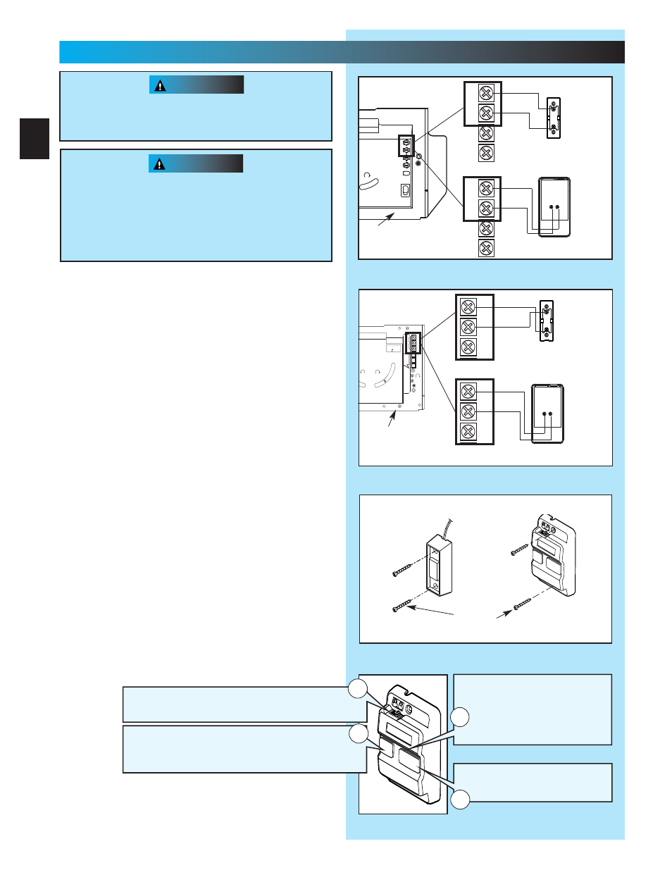
Independent Light Control
–
Controls door operator lights from inside garage
–
Energy-Saver shut-off turns off light 5 minutes after
door activation
Vacation Locking Switch
–
LOCK disables controls after door is completely closed
–
UNLOCK allows controls to work normally
Lighted Button
–
Shows system is powered
–
Lights when Security Lock
Switch is in UNLOCK position
–
Goes out when Security Lock
Switch is in LOCK position
Door Control Button
–
Open and closes door from
inside garage
1
4
3
2