Open yellow parts bag, Caution – Genie Pro max PMX-IC B Series User Manual
Page 17
CAUTION
ket m
ge
fr
Do Not fasten to drywall, particle board,
9. Mount po
TERNATE
MOUNTING METHODS).
•
Be sure rail assembly and power head are on
door center line (line
“
V
”
).
•
Check the illustrations. Decide which mounting
method you will use. Materials for mounting are
not included.
•
After power head is installed, remove
supporting material.
•
Close door.
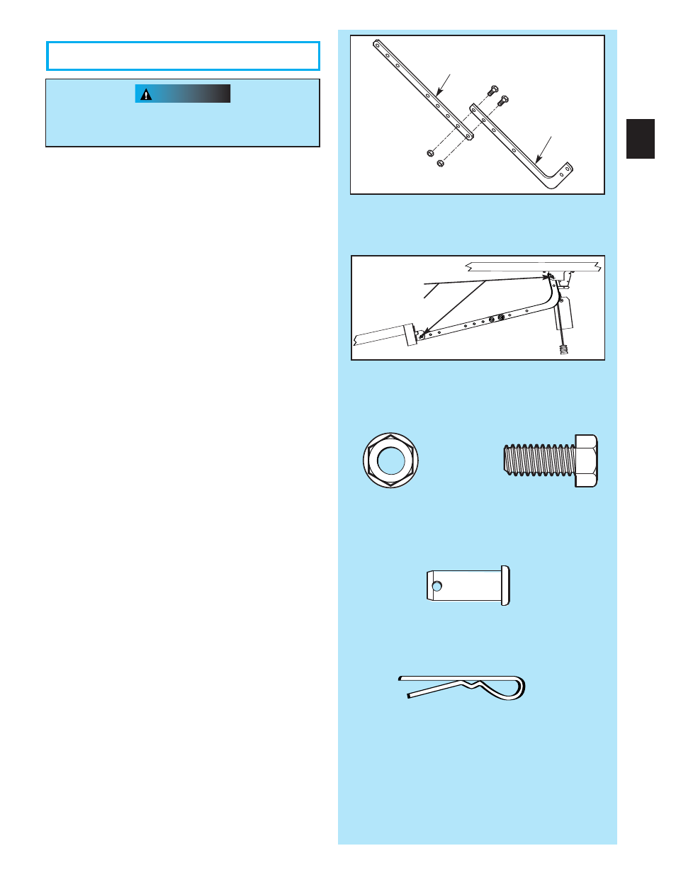
10.
xactly as shown (Fig. 2-16).
•
Overlap arms by two (2) holes.
•
Install two (2) 3/8
”
x 7/8
”
hex bolts, and hex
flange nuts.
•
Tighten hex nuts securely.
11. Install assemb
2-17).
•
Attach straight end of assembled door arms to
door bracket.
–
slip straight door arm into slot in door bracket.
–
secure with clevis pin [90] and cotter pin [89].
•
Release carriage (See emergency release tag).
•
Slide carriage toward door.
•
Attach short end of curved door arm to carriage.
–
slip curved door arm into slot in carriage.
–
secure with clevis pin and cotter pin.
NOTE:: WWhheen openniing, door muusst not ppaasss levvell
posiitiion or if yoouu aare not abblle to clloosse tthhe dooorr after
coommppllettinngg pprreeviious stteep; a loonnggeer door arrm is
reqquuiiredd.. Ann eextteensioonn kkit caan be ppuurrcchassedd bbyy
caalliing the CCusttoommeer Seerviicce pphhoonnee number,
1..8000..3554..3643.
12. Adjust emergenc
d length.
•
Mount the emergency release knob 6 feet from
the floor.
•
Retie overhand knot and trim excess cord.
Fig. 2-17
Fig. 2-16
Str
Cur
17
OPEN YELLOW PARTS BAG
[92]
[91]
Bolt, 3/8
”
-16 x 7/8
”
Nut, 3/8-16
[92] [91]
3/8-16 nut
Bolt, 3/8-16 x 7/8”
Clevis pin
[90]
[89]
[90]
Clevis pin
[89]
Cotter pin
d_39905_38124_14.0