Open blue parts bag, Caution, Shaft on top of power head (fig.1-2) – Genie Pro max PMX-IC B Series User Manual
Page 10: Fasten channel to power head, Do not, Attach emergency release tag (fig. 1-1), Shaft on top of power head (fig. 1-3)
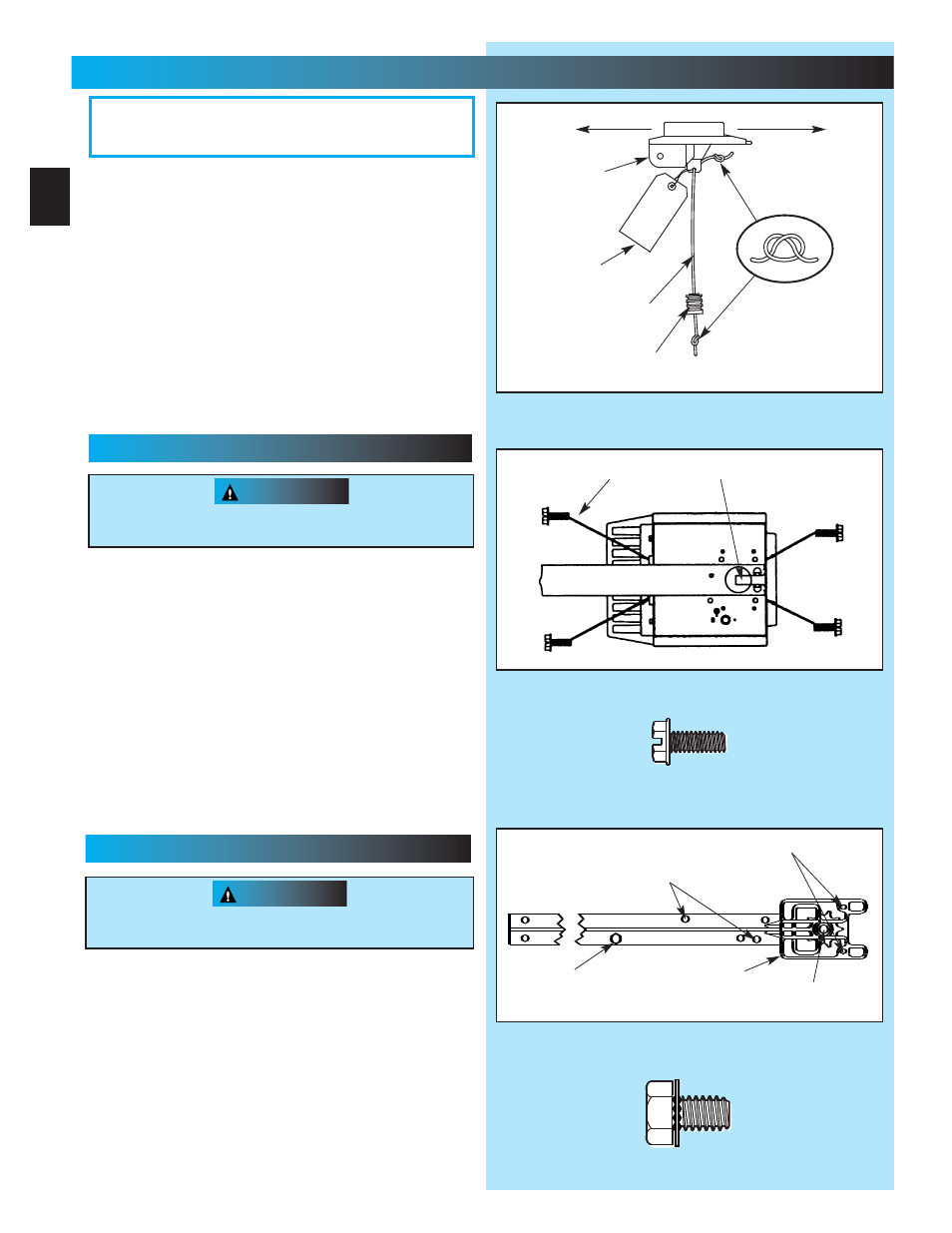
Fig. 1-3
No. 10-24 x 1/2
”
Hex Head Screws
5/16
”
x 1/2
”
Hex Head Screws
“
D
”
-Shaft and Hole
3. Place power head and channel on clean,flat surface.
4. Slide drive end of channel down over
“
D
”
-shaft on top of
power head (Fig.1-2).
•
Support header end of channel level with power head.
•
Slide carriage to align
“
D
”
-shaft with
“
D
”
-hole in sprocket.
•
Slide channel down
“
D
”
-shaft flush with power head.
5. Fasten channel to power head .
•
Align mounting holes in front and rear of power head frame.
•
Insert and securely tighten the four (4) No.10 x 1/2
”
hex
head screws [69].
NOOTTEE:: CChain iinnnnerr-sslidee oor bbeelltt buullett sshoouuld rremmaainn at
mid--traavel when aasssemblingg to power hheeaad to providee ppropeer
trraveel whhenn setttiinng lliimmiitts.
1. Attach emergency release knob cord (Fig. 1-1).
•
Tie overhand knot in end of cord.
•
Thread cord through knob so knot is inside knob.
•
Thread cord through hole in carriage lever.
•
Tie overhand knot in other end of cord.
Do Not
cut cord until after power head is mounted.
2. Attach emergency release tag (Fig. 1-1).
•
Thread wire through hole in carriage lever.
•
Wrap wire around itself, tie securely.
PLEASE NOTE THE ASSEMBLY PROCEDURES
ARE DIFFERENT FOR RAIL AND CHANNEL. BE
SURE TO FOLLOW THE APPLICABLE STEPS.
Fig. 1-2
Fig. 1-1
Do Not
attempt to run power head or to set limits until
operator is fully assembled and attached to the door.
“
D
”
-Shaft and Hole
Hex Head Screws
Carriage Stop
CAUTION
Do Not
attempt to run power head or to set limits until
operator is fully assembled and attached to the door.
Toward Door
Toward Power Head
Carriage
No. 10 x 1/2
”
Hex Head Screw
5/16
”
x 1/2
”
Hex Head Washer Screw
Emergency
Release
Tag
Emergency
Release
Cord
Emergency
Release
Knob
Sprocket Saddle
11
...........
OOOPPEERRRRAAAATTTOOORR AAAASSSSSSEEMMMMBBLLYYY
FFOOR HELP--1.800..3554.364433 OOR GENIEECOOMPANY.COOM
10
CCCCHHAANNNNNNEEEELL &&& PPPPOOOOWWW
WEERRR HHHHEEAADD AASSSSSSSSEEEMMBBLLLLYYY
RRAIL && PPOOWEERR HHEEAAD ASSEMBLY
3. Place power head and rail on clean, flat surface.
4. Slide drive end of rail down over
“
D
”
-shaft on top
of power head (Fig. 1-3).
•
Support header end of rail level with power head.
•
Slide carriage enough to align
“
D
”
-shaft with
“
D
”
-hole
in sprocket.
•
Slide rail down
“
D
”
-shaft flush with power head.
drags on the rail
CAUTION
OPEN BLUE PARTS BAG
Screws for attaching light cover are included in this
bag. Please set aside for use later.
[69]
[112]
[69]
[69]
[112]