Reference calculations, Legend, Troubleshooting – WaterFurnace 7 Series User Manual
Page 41: Troubleshooting reference calculations legend, Aurora control system, Refrigerant systems
41
7 SERIES 50Hz 700A11 INSTALLATION MANUAL
Aurora Control System
NOTE: Refer to the Aurora Base Control Application and
Troubleshooting Guide and the Instruction Guide: Aurora
Interface and Diagnostics (AID) Tool for additional information.
To check the unit control board for proper operation:
1. General
Check
• If any new device was installed, or any wiring
was changed, check the connections to ensure
the wiring is correct, and all the wires are in
good condition.
• Verify all the plugs are securely connected and in
good condition.
• Check the DIP switch (SW2) positions are correct.
• Measure 24 VAC between R and C. (The actual
reading may be from 18 to 30 VAC). Check the
incoming power and the power transformer if
the R and C voltage reading is not correct.
2.
No LEDs are On
• Check 24 VAC on board.
• Check the 3 amp fuse. Replace the fuse if needed.
• Verify transformer circuit breaker has not tripped
if no low voltage is present.
• Disconnect the thermostat connection P1.
• Replace the Aurora base control board.
Troubleshooting
Reference Calculations
Legend
Refrigerant Systems
Refrigerant pressures are monitored by the control
system; to maintain sealed circuit integrity, do not install
service gauges unless pressure sensor is suspected to be
inoperative. Compare the change in temperature on the
air side as well as the water side to the Unit Operating
Parameters tables. If the unit’s performance is not within
the ranges listed, make sure the airflow and water flow are
correct. Check superheat and subcooling with an AID Tool. If
superheat and subcooling are outside recommended ranges,
an adjustment to the refrigerant charge may be necessary.
NOTE: Refrigerant tests must be made with hot water
generator turned “OFF”. Verify that air and water flow rates
are at proper levels before servicing the refrigerant circuit.
NOTE: * When using water. Use 4.1 for 15% methanol/water
or Environol solution.
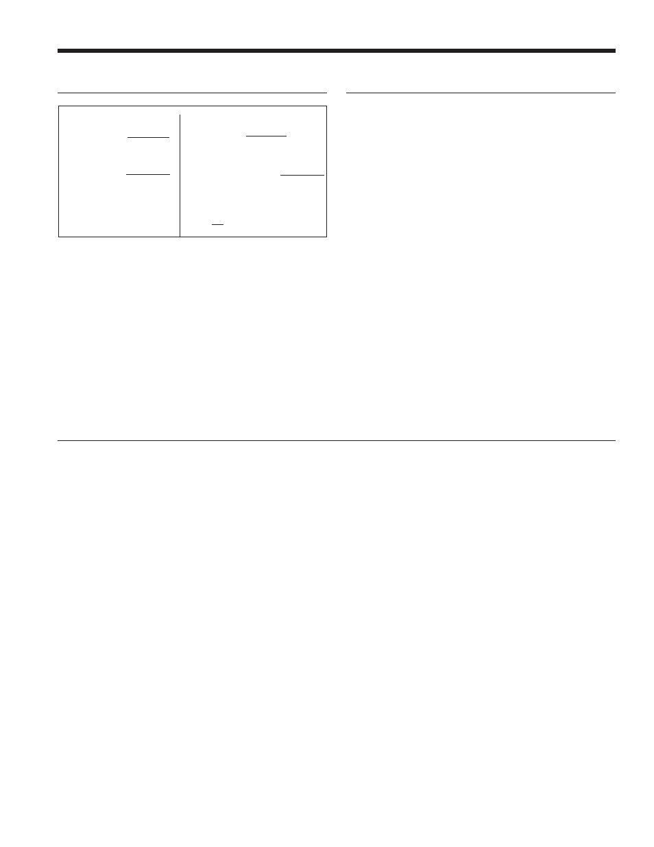
Heating Calculations:
Cooling Calculations:
LWT = EWT +
LAT (DB) = EAT (DB) -
LC = TC - SC
S/T =
HR
WF x 500
SC
AF x 1.08
SC
TC
LWT = EWT -
LAT = EAT +
TH = HC + HW
HE
WF x 500
HC
AF x 1.08
ABBREVIATIONS AND DEFINITIONS:
COP
= coefficient of performance
EER
= cooling energy efficiency (TC/kW)
ELT
= entering load fluid temperature
EST
= entering source fluid temperature to heat pump
FLA
= full load amps
FtHd = pressure drop in feet of head
gpm
= US gallon per minute
HC
= heating capacity in kW
HE
= heat of extraction in kW
HR
= heat rejected in kW
kPa =
kilopascal
kW =
kilowatt
L/s
= liters per second
LLT
= leaving load fluid temperature from heat pump
LRA
= locked rotor amps (starting current)
LST
= leaving source fluid temperature from heat pump
LWPD = load heat exchanger water pressure drop
MCC = maximum continuous current
PD =
pressure
drop
psi
= pressure drop in pounds per square inch
P/T =
Pressure/Temperature
RLA
= run load amps
TC
= total cooling capacity in kW
W =
Watt