Wiring schematics cont, Aurora variable speed drive/eev wiring cont, Danfoss eev control – WaterFurnace 7 Series User Manual
Page 35: Legend
35
7 SERIES 50Hz 700A11 INSTALLATION MANUAL
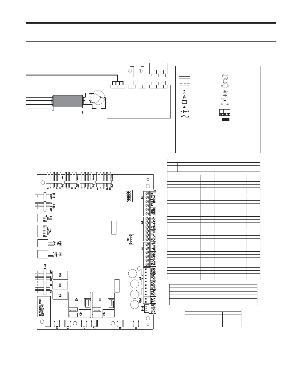
Aurora Variable Speed Drive/EEV Wiring cont.
Wiring Schematics cont.
T1
T3
T2
Red
Black
Suction Temp
KM2
1
2
EEV Output
KM9
1
2
3
4
GND
S2
12 VDC
X1
X2
Y1
Danfoss EEV
Control
Power
KM4
1
2
3
4
R
B+
A-
C
Leaving Air Temp
(LAT)
KM3
1
2
GND
S2
5
T
Black
Black
T
Black
Black
Suction
Line Temp
Discharge
Air Temp
Y2
1
2
3
4
+
X1
X2
Y1
5Y
2
Orange
Red
Yellow
Black
Gray
Bipolar Stepper Motor
VS Compressor
Blue
Metal
Flexible
Conduit
Green
2/15/13
97P842-11B
AXB™
SW1
Red Connector (4 Pin)
Current Transducer (CT)
Thermistor
Light emitting diode - Green
Relay coil
Capacitor w/ bleed resistor
Switch - Condensate overflow
Switch - High pressure
Switch - Low pressure
Polarized connector
Factory Low voltage wiring
Factory Line voltage wiring
Field low voltage wiring
Field line voltage wiring
Optional block
DC Voltage PCB traces
Junction
Quick connect terminal
Wire nut
Field wire lug
Ground
Fuse
CC -
CO -
K5 -
K6 -
CR3 -
CR4 -
F1 and F2 -
WCL -
HE -
HP -
LP -
PB1, PB2 -
PS -
RV -
SW1 -
SW1 -
SW2 -
TS -
Compressor Contactor
Condensate overflow sensor
DHW pump relay
Loop pump relay
Fuses
Water Coil Limit Sensor
Heater element
High pressure switch
Low pressure switch
Power blocks
Power strip
Reversing Valve coil
DIP package 5 position AXB
TEST MODE ABC Board
DIP package 8 position ABC Board
Thermal limit switch
Legend
Relay Contacts-
N.O., N.C.
G
T
1
3
2
P
L1
PSC Fan Speed Relay
PSC Fan Power Relay
ER1 to ER4 -
Aux heat stage relays
HWL -
Hot water limit sensor
SC -
Start Contactor
Start Relay
SR -
CS -
Compressor Solenoid
SW1-4
SW1-5 DESCRIPTION
ON
ON
Cycles with Blower
OFF
ON
Cycles with CC Įrst stage compressor or compressor spd 1-12
ON
OFF
Cycles with CC2 second stage of compressor or comp spd 7-12
OFF
OFF
Cycles with DH from ABC board
AXB Accessory 2 DIP Seƫngs
DESCRIPTION
SW2-4
SW2-5
Cycle with Blower
ON
ON
Cycle with Compressor
OFF
OFF
Water Valve Slow Opening
ON
OFF
Cycle with Comm. T-stat Hum Cmd
OFF
ON
ABC SW2 Accessory Relay
Slow Flash
Fast Flash
Flash Code
Flash Code 19
Alarm - Low Loop Pressure
Flash Code 21
Fault - Communication ECM Fan Motor Error Flash Code 22
Fault - Discharge Temperature Sensor
Flash Code 51
Fault - Suction Pressure Sensor
Flash Code 52
Fault - Critical Communication Error
Flash Code 53
Safe Mode - Ambient Temperature Sensor
Flash Code 49
Future Use
Flash Code 17
Non-Critical Communication Error
Flash Code 18
Alarm - Hot Water
Flash Code 15
Fault Variable Speed Pump
Flash Code 16
Fault LED (LED 1, Red) Cont.
ESD
Flash Code 6
Future Use
Flash Code 7
Flash Code 3
Future Use
Flash Code 4
Load Shed
Flash Code 5
Reserved
Flash Code 6
Condensate Overflow Lockout
Flash Code 7
Over/Under Voltage Shutdown
Flash Code 8
Future Use
Flash Code 9
Compressor Monitoring
Flash Code 10
Fault- FP1 and FP2 Sensor Error
Flash Code 11
Future Use
Flash Code 12
Non-Critical AXB Sensor Error
Flash Code 13
Critical AXB Sensor Error
Flash Code 14
Flash Code 2
Freeze Detection - FP1
Flash Code 5
Flash Code 2
Low Pressure Lockout
Flash Code 3
Freeze Detection- FP2
Flash Code 4
High Pressure Lockout
Future Use
Dehumidification Mode
DIP Switch Overide
Slow Flash
Status LED (LED 3, Green)
Normal Mode
ON
Control is Non - Functional
OFF
Test Mode
Slow Flash
Lockout Active
Fast Flash
Aurora LED Flash Codes
1 second on and 1 second off
No Software Overide
OFF
100 milliseconds on and 100 milliseconds off
100 milliseconds on and 400 milliseconds off with a 2 second pause before repeating
Random Start Delay (Alternating Colors)
Status LED (LED1, Green)
Fast Flash
Configuration LED (LED 2, Yellow)
Fast Flash
Fault LED (LED 3, Red)
Fast Flash
Configuration LED (LED 2, Yellow)
Fault LED (LED 1, Red)
Normal Mode
OFF
Input Fault Lockout
Flash Code 1
Derate - Drive Temperature
Flash Code 41
Derate - High Discharge Temperature
Flash Code 42
Derate - Low Suction Temperature
Flash Code 43
Alarm - Home Automation 1
Flash Code 23
Alarm - Home Automation 2
Flash Code 24
Fault - EEV Error
Flash Code 25
Safe Mode - EEV (Indoor) Communication
Flash Code 47
Safe Mode - EEV (Outdoor) Communication Flash Code 48
Derate - Low Condensing Pressure
Flash Code 44
Derate - High Condensing Pressure
Flash Code 45
Derate - Outer Power Limit
Flash Code 46
Fault - Over Current
Flash Code 56
Fault - Over/Under Voltage
Flash Code 57
Flash Code 54
Fault - Compressor Out of Envelope
Flash Code 55
Fault - Condensing Pressure Sensor
Fault - Low Supply Voltage
Safe Mode - Max Operating Pressure
Flash Code 74
Fault - Loss of Charge
Flash Code 71
Safe Mode - Suction Temperature Sensor
Flash Code 72
Safe Mode - LAT Temperature Sensor
Flash Code 73
Fault - High Drive Temperature
Flash Code 58
Fault - Drive Internal Error MOC/AOC
Flash Code 59
Fault - Multiple Safe Modes
Flash Code 61
Black