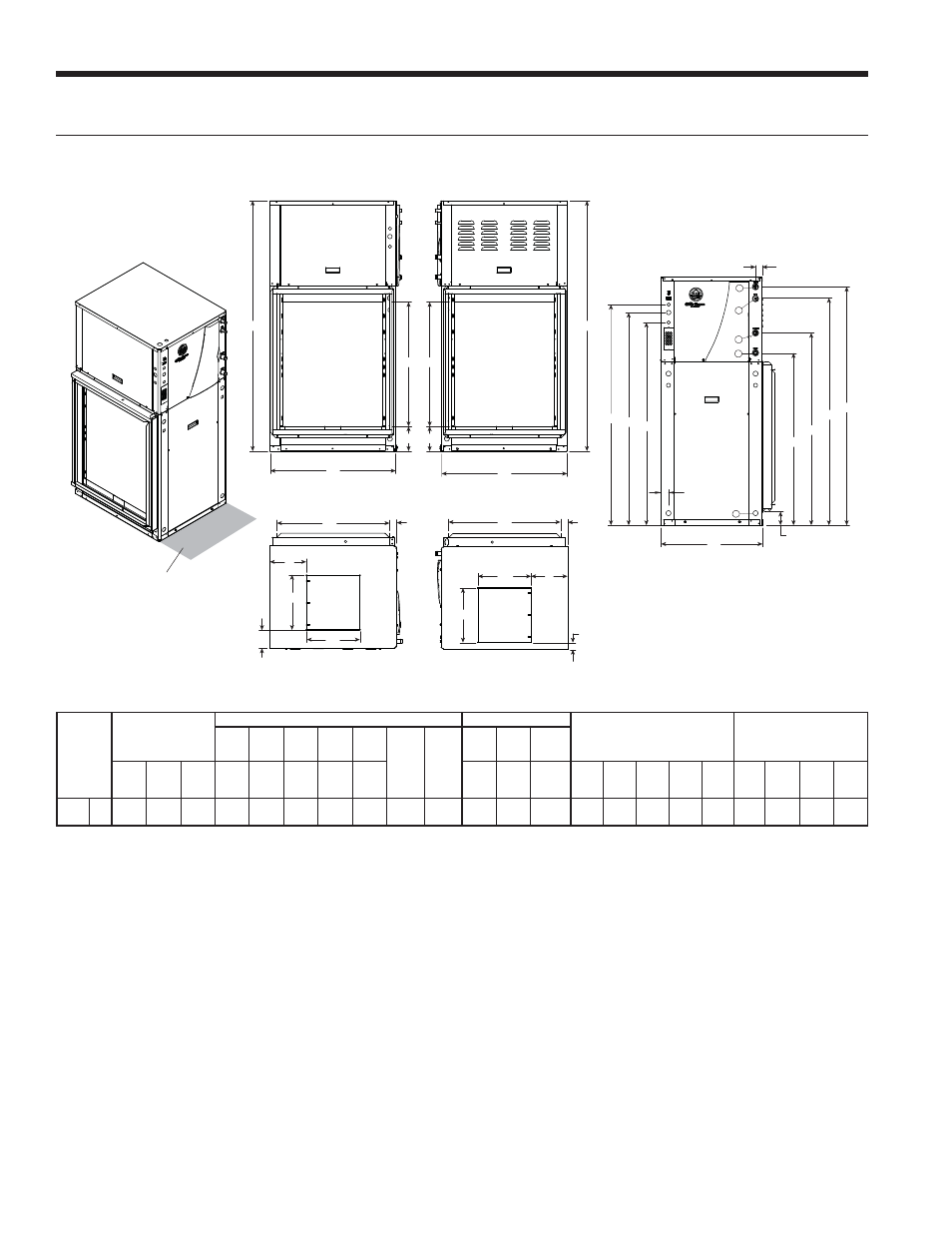
Vertical dimensional data cont, Bottom air discharge – WaterFurnace 7 Series User Manual
Page 18
18
7 SERIES 50Hz 700A11 INSTALLATION MANUAL
2 ft [61 cm]
Primary Service Access
LEFT SIDE
RIGHT SIDE
B
C
S
T
T
B
C
S
LEFT RETURN
RIGHT RETURN
R
Q
L
N
O
P
A
FRONT
D
E
F
G
H
J
K
I
1.90
(4.7 cm)
1.70
(4.3 cm)
1
2
3
4
5
RIGHT BOTTOM DISCHARGE
FLOOR FOOT PRINT
R
O
N
L
M
LEFT BOTTOM DISCHARGE
FLOOR FOOT PRINT
Q
Bottom Air Discharge
Bottomflow
Models
Overall Cabinet
Water Connections
Electrical Knockouts
Discharge Connection
duct flange installed (± 2.54mm)
Return Connection
using std deluxe filter rack
(± 2.54mm)
1
2
3
4
5
Loop
Water
FPT
HWG
Sweat
(I.D.)
I
12.7mm
cond
J
12.7mm
cond
K
19.05mm
cond
A
Width
B
Depth
C
Height
D
In
E
Out
F
HWG
In
G
HWG
Out
H
Cond-
ensate
Low
Voltage
Ext
Pump
Power
Supply
L
M
N
Supply
Width
O
Supply
Depth
P
Q
R
Return
Depth
S
Return
Height
T
009-
015
cm.
64.8
80.0
158.8
110.2
122.9
144.8
152.4
7.9
25.4mm
Swivel
12.7mm
Female
129.8
141.2
136.1
23.1
12.2
34.0
34.5
4.3
4.6
71.4
86.4
14.2
Condensate is 19.05mm PVC female glue socket and is switchable from side to front
Unit shipped with deluxe 5.08cm (field adjustable to 2.54cm) duct collar/filter rack extending from unit 8.255cm and is suitable for duct connection.
Decorative molding and/or water connections extend 30.5mm beyond front of cabinet.
Louvered vents in the compressor section right side access panel extend 12.7mm from side of cabinet. Allow clearance for venting.
5/29/13
Vertical Dimensional Data cont.