Vlan network, Bridge network, Vlan network bridge network – Ubiquiti Networks Rockeac User Manual
Page 27
24
Chapter 4: Network
airOS®7 User Guide
Ubiquiti Networks, Inc.
•
Comment
You can enter a brief description of the
purpose for the IP alias.
Click OK to save changes, or click Cancel to close the
window without saving changes.
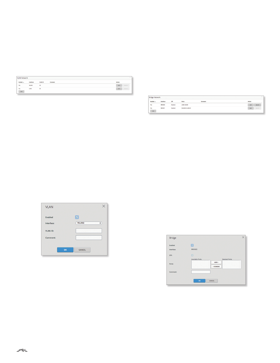
VLAN Network
(Available in Advanced view.) You can create multiple
Virtual Local Area Networks (VLANs). Click the VLAN
Network section to display its contents.
Enabled
Displays the status of the VLAN, Yes or No.
Interface
Displays the name of the interface.
VLAN ID
Displays the VLAN identifier.
Comment
Displays a brief description of the purpose for
the VLAN.
Add
Click Add to create a VLAN. Go to the Add or Edit a
VLAN section below.
Action
After a VLAN has been created, you have the
following options:
•
Edit
Make changes to a VLAN. Go to the Add or Edit a
VLAN section below.
•
Delete
Remove a VLAN. (A VLAN configured as the
management interface cannot be deleted.)
Add or Edit a VLAN
The VLAN window opens:
•
Enabled
Select this option to enable the specific
VLAN. All the added VLANs are saved in the system
configuration file; however, only the enabled VLANs are
active on the device.
•
Interface
Select the appropriate interface.
•
VLAN ID
Enter the VLAN ID, a unique value assigned to
each VLAN at a single device; every VLAN ID represents
a different VLAN. The VLAN ID range is 2 to 4094.
•
Comment
You can enter a brief description of the
purpose for the VLAN.
Click OK to save changes, or click Cancel to close the
window without saving changes.
Bridge Network
(Available in Advanced view.) You can create one or
more bridge networks if you need complete Layer 2
transparency. This is similar to using a switch – all traffic
flows through a bridge, in one port and out another
port, regardless of VLANs or IP addresses. For example,
if you want to use the same IP subnet on both sides of a
device, then you create a bridge network. There are many
different scenarios that could require bridged interfaces,
so the Bridge Network section is designed to allow
flexibility.
Click the Bridge Network section to display its contents.
Enabled
Displays the status of the bridge network,
Enabled (Yes) or Disabled (No).
Interface
Displays the name of the interface.
STP
Displays the STP status, Enabled or Disabled.
Ports
Displays the ports used for the bridge network.
Comment
Displays a brief description of the purpose for
the bridge network.
Add
Click Add to create a bridge network. Go to the Add
or Edit a Bridge Network section below.
Action
After a bridge network has been created, you have
the following options:
•
Edit
Make changes to a bridge network. Go to the Add
or Edit a Bridge Network section below.
•
Delete
Remove a bridge network. (A bridge configured
as a management interface cannot be deleted.)
Add or Edit a Bridge Network
The Bridge Network window opens:
•
Enabled
Select this option to enable the specific bridge
network. All the added bridge networks are saved in the
system configuration file; however, only the enabled
bridge networks are active on the device.
•
Interface
Displays the name of the interface.