3 differential field wiring – Spectrum Controls 140 ACI 051 00sc User Manual
Page 40
Installation Instructions
32-Channel Analog Input Module
Quantum Series 140 AxI 05x 00sc
35
5.3
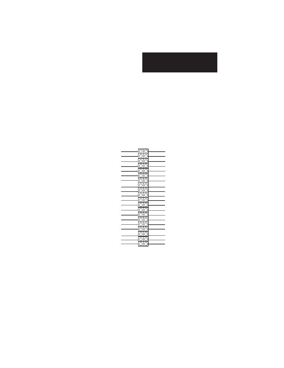
Differential Field wiring
Differential mode performs a software difference of two consecutive
channel inputs, and reports the data on the first channel register of the
pair. The second channel’s output is zero. The data acquisition between
the two channels is not synchronized so common mode noise on the signal
pair may not be fully removed, however DC offsets should be compen-
sated for correctly.
+ Note: The channel pairs are not being measured simultaneously, this could lead to an error in the
actual differential value that is calculated.
7
16
1
3
5
9
11
13
15
17
19
21
23
25
27
29
31
33
35
37
39
2
4
6
8
10
12
14
18
20
22
24
26
28
30
32
34
36
38
40
(IN+)6
(IN+)2
(IN+)1
COM GROUP 1
(IN-)3
(IN+)5
(IN-)8
(IN+)14
(IN-)19
(IN-)9
COM GROUP 3
(IN-)11
(IN+)13
(IN-)12
(IN-)16
(IN-)15
COM GROUP 4
(IN-)8
(IN-)7
COM GROUP 2
COM GROUP 4
(IN+)16
(IN+)15
COM GROUP 2
(IN+)8
(IN+)7
(IN-)28
(IN+)10
(IN+)9
(IN+)11
(IN+)12
(IN-)13
COM GROUP 3
(IN-)6
(IN-)2
(IN-)1
(IN+)3
(IN+)4
(IN-)5
COM GROUP 1
+ Note: Differential mode only applies to voltage inputs.