Chapter 5 installation – Spectrum Controls 140 ACI 051 00sc User Manual
Page 36
Installation Instructions
32-Channel Analog Input Module
Quantum Series 140 AxI 05x 00sc
31
Chapter 5
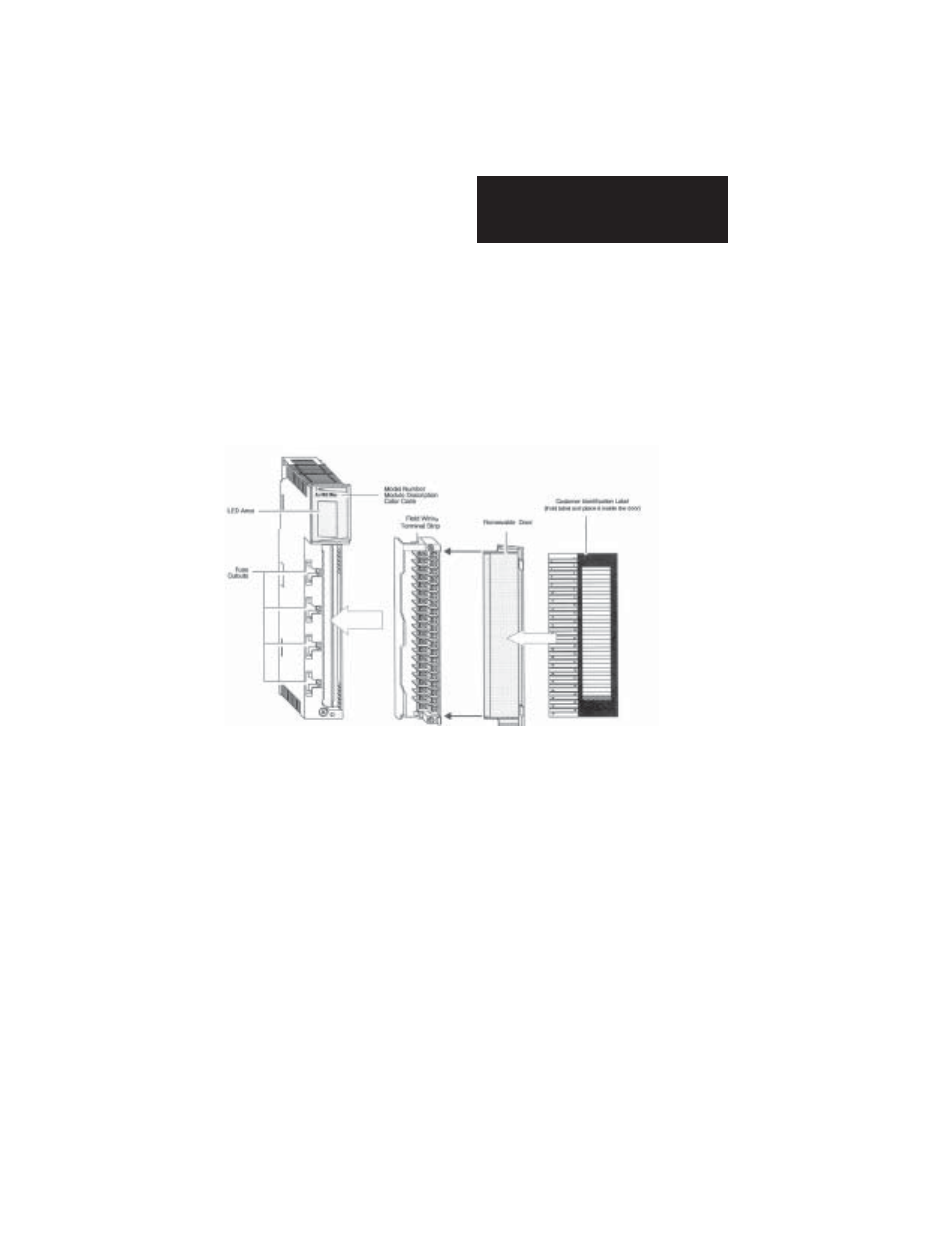
INSTALLATION
+ Note: When field wiring the I/O modules, the maximum wire size that should
be used is 1-14 AWG or 2-16 AWG; the minimum size is 20 AWG.
+ Note: The field wiring terminal block (Modicon # 140 XTS 002 00) or the 140
CFA040 00 40 pin Cablefast Terminal block must be ordered sepa-
rately. (The terminal block includes the removable door label.)
+ Note: Power, input and output (I/O) wiring must be in accordance with Class
1, Division 2 wiring methods [Article 501-4 (b) of the National
Electrical Code, NFPA 70] and in accordance with the authority
having jurisdiction.”
+ Note: Peripheral equipment must be suitable for the location in which it is
used.