Spectrum Controls 1769sc-HART Modules User Manual
Page 63
Chapter 4: Module Data, Status, and Configuration
User's Manual 0300215-03 Rev. A
6-13
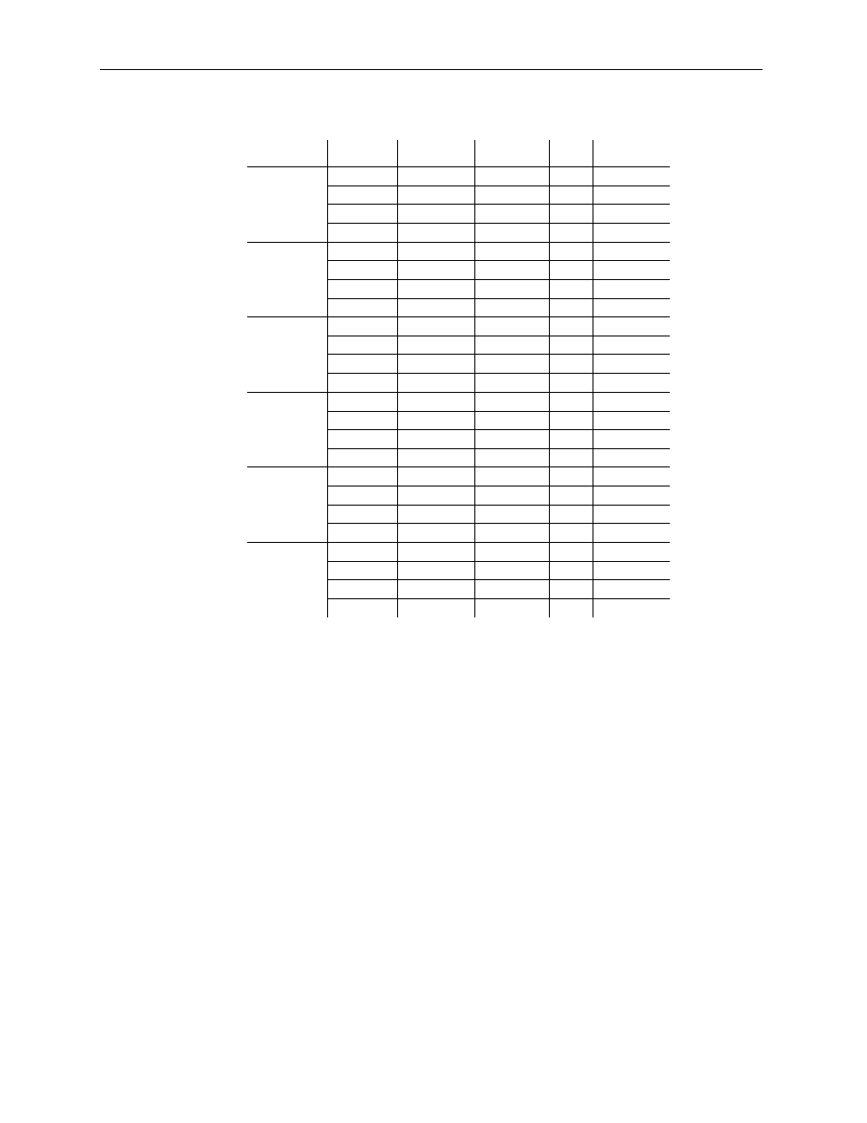
Table 6-8 (Data Formats)
Input Range:
Signal:
RAW/
Proportional
Engineering
Units
PID
% Full Scale
-10 to +10V
-10.500V -32767
-10500
-410 -10500
-10.000V -31207
-10000
0
-10000
+10.000V 31207
10000
16383
10000
+10.500V 32767
10500
16793
10500
0 to 5V
-0.500V -32767
-500
-1638
-1000
+0.000V -27068
0
0 0
+5.000V 29646
5000
16383
10000
+5.250V 32767
5250
17202
10500
0 to 10V
-0.500V -32767
-500
-819
-500
+0.000V -29788
0
0 0
+10.000V 29646
10000
16383
10000
+10.500V 32767
10500
17202
10500
4 to 20mA
+3.200mA -32767
3200
-819 -500
+4.000mA -29822
4000
0
0
+20.000mA 29085
20000
16383 10000
+21.000mA 32767
21000
17407 10625
1 to 5V
+0.500V -32767
500
-2048
-1250
+1.000V -25869
1000
0 0
+5.000V 29318
5000
16383
10000
+5.250V 32767
5250
17407
10625
0 to 20mA
+0.000mA -32767
0
0
0
+0.000mA -32767
0
0
0
+20.000mA 29646
20000
16383 10000
+21.000mA 32767
21000
17202 10500
6.4.5
Process Alarm High Setpoint (Words 4, 10, 16, 22)
The user defines the process alarm high value using this signed word element. The range
of this value is dictated by the selected data format. When the measured analog signal for
the associated channel exceeds the high process alarm, an alarm bit will be set in the
input data table that corresponds to the associated channel. See Input Type and Data
Format (Words 3, 9, 15, 21) for more information regarding data format.
6.4.6
Process Alarm Low Setpoint (Words 5, 11, 17, 23)
The user defines the process alarm low value using this signed word element. The range
of this value is dictated by the selected data format. When the measured analog signal for
the associated channel drops below the low process alarm, an alarm bit will be set in the
input data table that corresponds to the associated channel. See Input Type and Data
Format (Words 3, 9, 15, 21) for more information regarding data format.
6.4.7
Process Alarm Deadband (Words 6, 12, 18, 24)
The deadband is a range through which the measured input may be varied without
initiating an alarm response. The deadband will use the data format selected in the
channel configuration. See Input Type and Data Format (Words 3, 9, 15, 21) for more
information regarding input type and format. The deadband is added to the low alarm
value and subtracted from the high alarm value. In both cases, the resulting value must