6 wiring diagram, 7 calibration – Spectrum Controls 1769sc-HART Modules User Manual
Page 28
Compact IO™ Isolated HART Analog Input Module
User's Manual 0300215-03 Rev. A
3-10
5.
Connect the signal wires to the terminal block. Connect the other end of the cable to
the analog input device.
6.
Repeat steps 1 through 5 for each channel on the module.
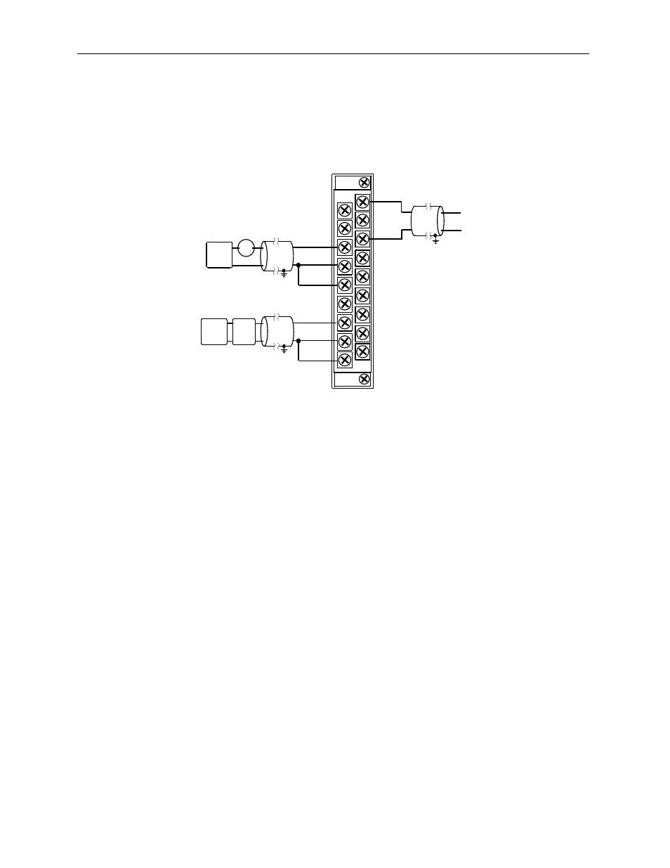
3.7.6
Wiring Diagram
Figure 3-7
N/C
Ch1-iRtn
N/C
Ch3-iRtn
Ch0+
N/C
Ch0-iRtn
Ch0-
Ch1+
N/C
Ch2-iRtn
Ch2-
Ch3+
Ch3-
N/C
N/C
Ch2+
Ch1-
+ -
2 Wire
XMTR
+
-
24V DC
Power
Supply
2 Wire Current Input
+
-
4 Wire Current Input
4 Wire
XMTR
+
+
-
-
24V DC
Power
Supply
+V
- V
Voltage Input
3.7.7
Calibration
The isolated HART module is initially calibrated at the factory.