Spectrum Controls 1769sc-HART Modules User Manual
Page 61
Chapter 4: Module Data, Status, and Configuration
User's Manual 0300215-03 Rev. A
6-11
Slot Variable Enable (Bits 4 through 7)
Slot variable enable bits 4 through 7 can be used to enable HART slot variables 0 through
3, respectively, for the connected HART device. The variable code which is used to
define each slot variable for each associated channel is entered into configuration words
26 through 33. Refer to section 6.4.9 for more information regarding configuring slot
variables.
Note: Slot variables are not supported by all HART devices.
Note: Slot codes must be enabled in sequential order. For example, SV0 (Enabled),
SV1 (Disabled), and SV2 (Enabled), is not a valid configuration. In this case, all three
slot variables would be enabled.
EI (Enable Interrupt)
Allows each channel’s process alarm interrupts to be enabled.
AL (Alarm Latch)
Allows latching of each channel’s process alarms to be enabled.
EA (Enable Alarm)
Enable process alarming on the associated channel.
Reserved
Reserved for future expansion and should be set to zero.
EC (Enable Channel)
Enable associated channel.
6.4.4
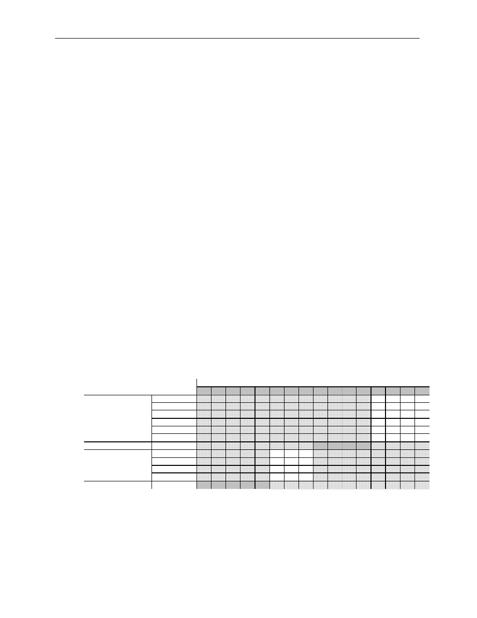
Input Type and Data Format (Words 3, 9, 15, 21)
This section of the configuration allows the user to define the input type (i.e. 0 to 20mA,
4 to 20 mA, 0 to 10VDC, etc) and the data format for the associated channel.
Table 6-7 (Input Type and Data Format)
15
14
13
12
11
10
9
8
7
6
5
4
3
2
1
0
-10 to +10V
0
0
0
0
0 to 5V
0
0
0
1
0 to 10V
0
0
1
0
4 to 20mA
0
0
1
1
1 to 5V
0
1
0
0
0 to 20mA
0
1
0
1
Reserved
Set To Zero
0
0
0
0
Raw/Proportional
0
0
0
Engineering Units
0
0
1
Scaled for PI D
0
1
0
Percent Range
0
1
1
Reserved
Set To Zero
0
0
0
0
0
To Select
Make these bit settings
Input Type
Data Type
Input Type
Allows the user to configure the input type and range for the associated channel.
Note: To enable HART you must select the 4 to 20 mA range.