Spectrum Controls 1769sc-HART Modules User Manual
Page 24
Compact IO™ Isolated HART Analog Input Module
User's Manual 0300215-03 Rev. A
3-6
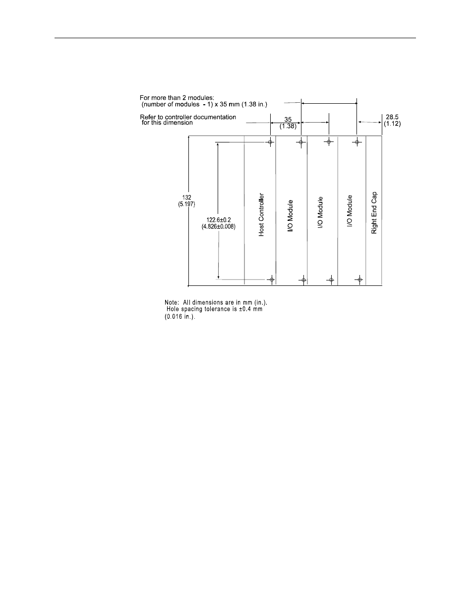
Panel Mounting Using the Dimensional Template
Figure 3-4
Panel Mounting Procedure Using Modules as a Template
The following procedure allows you to use the assembled modules as a template for
drilling holes in the panel. If you have sophisticated panel mounting equipment, you can
use the dimensional template provided on the previous page. Due to module mounting
hole tolerance, it is important to follow these procedures:
1.
On a clean work surface, assemble no more than three modules.
2.
Using the assembled modules as a template, carefully mark the center of all module-
mounting holes on the panel.
3.
Return the assembled modules to the clean work surface, including any previously
mounted modules.
4.
Drill and tap the mounting holes for the recommended M4 or #8 screw.
5.
Place the modules back on the panel, and check for proper hole alignment.
6.
Attach the modules to the panel using the mounting screws.
NOTE If mounting more modules, mount only the last one of this group and put the
others aside. This reduces remounting time during drilling and tapping of the next
group.
7.
Repeat steps 1 to 6 for any remaining modules.
3.5.3
DIN Rail Mounting
The module can be mounted using the following DIN rails:
•
35 x 7.5 mm (EN 50 022 - 35 x 7.5), or
•
35 x 15 mm (EN 50 022 - 35 x 15).