Spectrum Controls 1769sc-HART Modules User Manual
Page 14
Chapter 2: Quick Start for Experienced Users
User's Manual 0300215-03 Rev. A
2-2
Step 1: Ensure that your 1769 system
power supply
1
has sufficient current
output to support your system
configuration. Reference
Chapter 3 (Installation and Wiring)
The modules maximum current draw is shown below:
5V dc
24V dc
175 mA
60 mA
NOTE: The module cannot be located more than 8 modules away from the system
power supply.
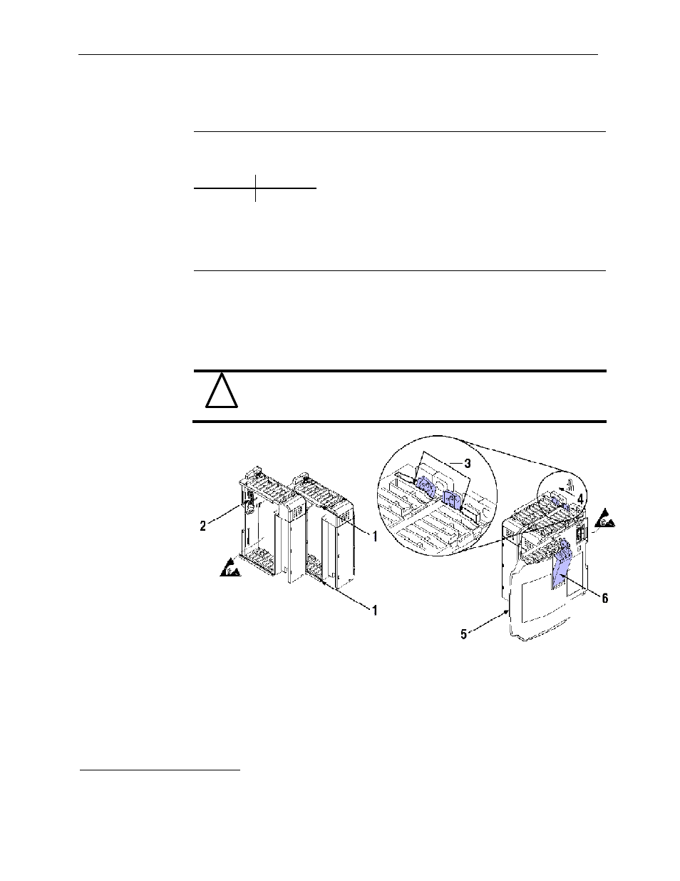
Step 2: Attach and lock the module.
Reference
Chapter 3 (Installation and Wiring)
Remove power before removing or inserting this module. If you remove or insert a
module with power applied an electrical arc may occur.
NOTE: The module can be panel or DIN rail mounted. Modules can be assembled
before or after mounting.
!
Attention
Remove power before removing or inserting this module. If you remove
or insert a module with power applied an electrical arc may occur.
1.
Check that the bus lever of the module to be installed is in the unlocked (fully right)
position.
2.
Use the upper and lower tongue-and-groove slots (1) to secure the modules together
(or to a controller).
3.
Move the module back along the tongue-and-groove slots until the bus connectors
(2) line up with each other.
4.
Push the bus lever back slightly to clear the positioning tab (3). Use your fingers or a
small screwdriver.
1
The system power supply could be a 1769-PA2, -PB2, -PA4, -PB4, or the internal supply of the MicroLogix 1500
packaged controller.