Spectrum Controls 1769sc-HART Modules User Manual
Page 22
Compact IO™ Isolated HART Analog Input Module
User's Manual 0300215-03 Rev. A
3-4
Section 3.4
System Assembly
The module can be attached to the controller or an adjacent I/O module before or after
mounting. For mounting instructions, see Panel Mounting Using the Dimensional
Template, or DIN Rail Mounting. To work with a system that is already mounted, see
Replacing a Single Module within a System.
The following procedure shows you how to assemble the Compact I/O system.
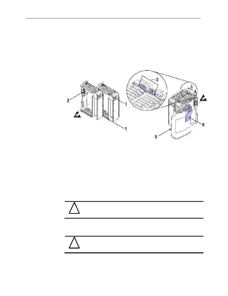
Figure 3-2
1.
Disconnect power.
2.
Check that the bus lever of the module to be installed is in the unlocked (fully right)
position.
NOTE: If the module is being installed to the left of an existing module, check that the
right-side adjacent module’s bus lever is in the unlocked (fully right) position.
3.
Use the upper and lower tongue-and-groove slots (1) to secure the modules together
(or to a controller).
4.
Move the module back along the tongue-and-groove slots until the bus connectors
(2) line up with each other.
5.
Push the bus lever back slightly to clear the positioning tab (3). Use your fingers or a
small screwdriver.
6.
To allow communication between the controller and module, move the bus lever
fully to the left (4) until it clicks. Ensure it is locked firmly in place.
!
Attention
When attaching I/O modules, it is very important that the bus
connectors are securely locked together to ensure proper electrical
connection.
7.
Attach an end cap terminator (5) to the last module in the system by using the
tongue-and-groove slots as before.
8.
Lock the end cap bus terminator (6).
!
Attention
A 1769-ECR or 1769-ECL right or left end cap respectively must be
used to terminate the end of the bus.