Spectrum Controls 1769sc-HART Modules User Manual
Page 41
User's Manual 0300215-03 Rev. A
Chapter 5
Configuring the IF4IH for a
MicroLogix 1500 Using
RSLogix 500
This chapter examines the 1769sc-IF4IH module’s addressing scheme and describes
module configuration using RSLogix 500 and a MicroLogix 1500 controller. This
chapter will cover the following:
•
Module Addressing
•
Configuring the IF4IH in a MicroLogix 1500 System
•
Using the Ladder Sample
Section 5.1
Module
Addressing
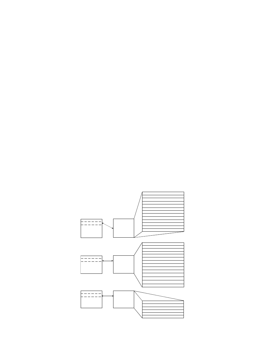
The following memory map shows the input, output, and configuration image tables for
the module. Detailed information on the image table is located in Chapter 6.
Figure 5-1 (Module Memory Map)
slot e
Input Image File
Input Image
72 Words
Memory Map
Word 0: Channel 0 Data Word
Word 1: Channel 1 Data Word
Word 2: Channel 2 Data Word
Word 3: Channel 3 Data Word
Word 4: Time Stamp Value
Word 5: General Channel Status
Word 6: Process & Range Alarms
Word 7: Pad
Words 8..27: HART Packet Data
Word 28: ScanMSG Slave Control
Word 29: ScanMSG Response Size
Words 30..49: ScanMSG Response Buffer
Bit 15
Bit 1
slot e
Configuration File
Configuration
34 Words
Words 2..7: Channel 0 Configuration
Words 8..13: Channel 1 Configuration
Words 14..19: Channel 2 Configuration
Words 20..25: Channel 3 Configuration
Bit 15
Bit 1
Word 1: Module Configuration
Word 0: Real Time Sample
slot e
Output File
Output
46 Words
Word 2: ScanMSG Master Control
Word 3: ScanMSG Request Size
Word 4..23: ScanMSG Request Buffer
Bit 15
Bit 1
Word 1: Last Packet Scanned
Word 0: Unlatch Alarms/HART Suspend
Word 26: Ch0 Slot Variables 0 & 1
Word 27: Ch0 Slot Variables 2 & 3
Word 28: Ch1 Slot Variables 0 & 1
Word 29: Ch1 Slot Variables 2 & 3
Word 30: Ch2 Slot Variables 0 & 1
Word 31: Ch2 Slot Variables 2 & 3
Word 32: Ch3 Slot Variables 0 & 1
Word 33: Ch3 Slot Variables 2 & 3
Words 50..71: Reserved
Word 24..45: Reserved