1 input data values (words 0 to 3), 2 time stamp value (word 4), 3 general status bits s0 to s3 (word 5) – Spectrum Controls 1769sc-HART Modules User Manual
Page 52
Compact IO™ Isolated HART Analog Input Module
User's Manual 0300215-03 Rev. A
6-2
Section 6.2
Accessing Input
Image File Data
The input image file represents data words and status words. Input words 0 through 3
hold the input data that represents the value of the analog inputs for channels 0 through 3.
These data words are valid only when the channel is enabled and there are no errors.
Input word 4 contains the time stamp value. Words 5 and 6 contain status information
for the four channels including process alarms and over and under range flags. Word 7
contains the HART channel identification and status information. Words 8 through 27
include the HART packet data. Refer to Chapter 7 for information on how to demultiplex
the HART packet data
.
Input word 28 holds the message control. Word 29 holds the
message response size. Words 30 through 49 hold the message response buffer. Refer to
Chapter 7 for more information regarding input words 28 through 49.
You can access the information in the input image file using the programming software
configuration screen. For information on configuring the module in a MicroLogix 1500
system using RSLogix 500, see Chapter 5; and for the CompactLogix using RSLogix
5000, see Chapter 4.
Section 6.3
Input Data File
The input data file allows you to access module input data for use in the control program,
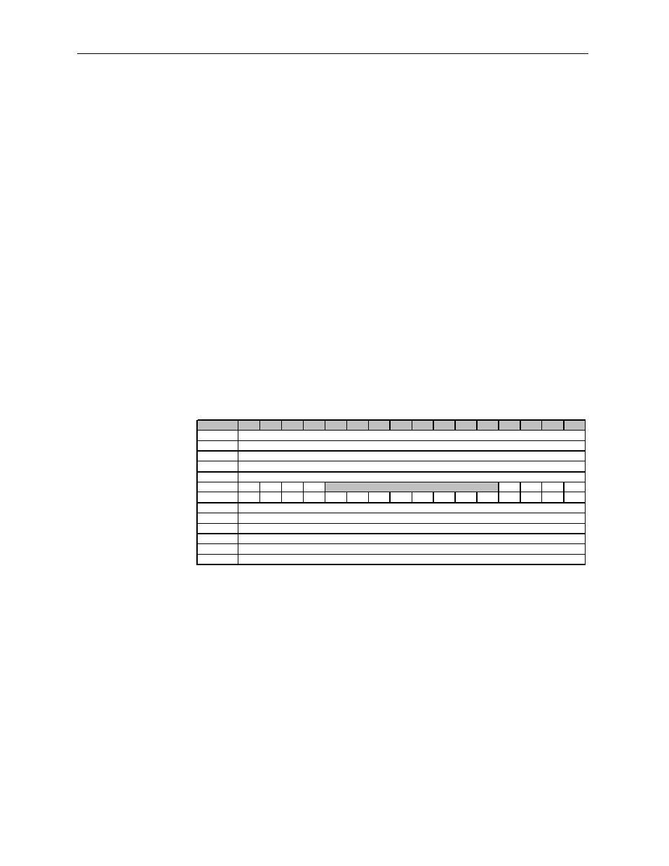
via word and bit access. The data table structure is shown in the table below.
Table 6-1 (Module Input Image)
Word/Bit
¹
15
14
13
12
11
10
9
8
7
6
5
4
3
2
1
0
0
1
2
3
4
5
OS3 OS2 OS1 OS0
S3
S2
S1
S0
6
L3
H3
U3
O3
L2
H2
U2
O2
L1
H1
U1
O1
L0
H0
U0
O0
7
8..27
28
29
30..49
50..71
(1) Changing bit values is not s upported by all cont rollers. Ref er to your controller manual for det ails.
Reserved
Time Stamp Value
Message Response Size
Not Used
Pad (16 bit alignment)
Message Response Buffer
Analog Input Data Channel 0
Analog Input Data Channel 1
Analog Input Data Channel 2
Analog Input Data Channel 3
HART Packet Data
Message Slave Control
6.3.1
Input Data Values (Words 0 to 3)
Data words 0 through 3 correspond to channels 0 through 3 and contain the converted
analog input data from the input device. The most significant bit, bit 15, is the sign bit
(SGN).
6.3.2
Time Stamp Value (Word 4)
The time stamp value represents the instant in time that the current input data was read.
The time stamp value is measured in milliseconds from 0 to 32767. When the value
reaches 32767, the timer will roll over to 0 and then the process will repeat.
6.3.3
General Status Bits S0 to S3 (Word 5)
Bits S0 through S3 of word 5 contain the general status information for channels 0
through 3, respectively. If set (1), this bit indicates an error (over- or under-range, low or
high alarm, or channel data not valid). The data not valid condition is described below.