Spectrum Controls 1769sc-HART Modules User Manual
Page 58
Compact IO™ Isolated HART Analog Input Module
User's Manual 0300215-03 Rev. A
6-8
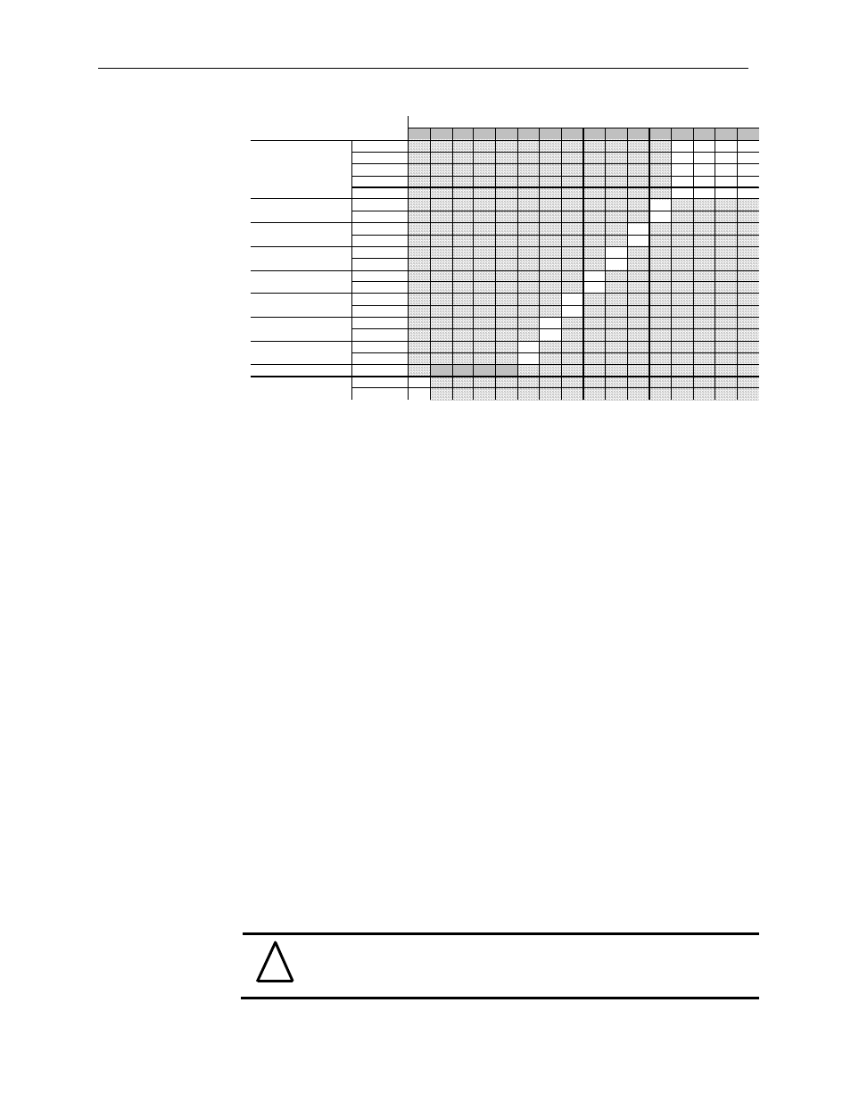
Table 6-4 (Filter Frequency and General Settings)
15
14
13
12
11
10
9
8
7
6
5
4
3
2
1
0
60 Hz
0
0
0
0
50 Hz
0
0
0
1
28.5 Hz
0
0
1
0
300 Hz
0
0
1
1
360 Hz
0
1
0
0
Disable
0
Enable
1
Disable
0
Enable
1
Disable
0
Enable
1
Disable
0
Enable
1
Disable
0
Enable
1
Disable
0
Enable
1
Disable
0
Enable
1
Reserved
Set To Zero
0
0
0
0
Disable
0
Enable
1
EI (E nable Interr upt)
AL (Alarm Latch)
EA (Enable Al arm)
T o Select
Make these bit settings
EC (Enabl e Channel)
Slot Code 0
Slot Code 1
Slot Code 2
Slot Code 3
Filter Frequency
Input Filter Selection (Bits 0 through 3)
Each channel can be configured for five different filter settings. Select one of the five
filters, for the associated channel.
Effects of Filter Frequency on Noise Rejection
The filter frequency that you choose for a module channel determines the amount of
noise rejection for the inputs. A lower frequency (50 Hz versus 300 Hz) provides better
noise rejection and increases effective resolution, but also increases channel update time.
A higher filter frequency provides lower noise rejection, but decreases the channel update
time and effective resolution.
When selecting a filter frequency, be sure to consider cut-off frequency and channel step
response to obtain acceptable noise rejection. Choose a filter frequency so that your
fastest-changing signal is below that of the filter’s cut-off frequency.
Common Mode Rejection is better than 60 dB at 50 and 60 Hz, with the 50 and 60 Hz
filters selected, respectively, or with the 28.5Hz filter selected. The module performs well
in the presence of common mode noise as long as the signals applied to the user positive
and negative input terminals do not exceed the common mode voltage rating (±500V) of
the module. Improper earth ground may be a source of common mode noise.
NOTE: Transducer power supply noise, transducer circuit noise, or process variable
irregularities may also be sources of normal mode noise.
Effects of Filter Frequency on Channel Step Response
The selected channel filter frequency determines the channel’s step response. The step
response is the time required for the analog input signal to reach 100% of its expected
final value, given a full-scale step change in the input signal. This means that if an input
signal changes faster than the channel step response, a portion of that signal will be
attenuated by the channel filter. The channel step response is calculated by a settling time
of 3 x (1/filter frequency).
!
Attention
The Real Time Sample rate must be greater than or equal to the slowest
channel step response time or a configuration error will occur.