SOR Calibration Manager Software User Manual
Page 3
3/12
Form 1459 (01.13) ©SOR Inc.
Text
InTERFaCE SET-up
n
Plug the USB cable into the USB receptacle of the Calibration Interface.
n
Plug the other end of the USB cable into a USB port on your computer. You
may see a “Found New Hardware” balloon appear in the system tray while the
computer installs the driver.
n
Do not unplug the Calibration Interface until the driver is finished installing.
n
Once the driver is finished installing, your Calibration Interface is ready to use.
n
Plug the other end of the USB cable into a USB port on your computer. You
may see a “Found New Hardware” balloon appear in the system tray while the
computer installs the driver.
NOTE: The Calibration Interface will power on, at which point, an audible clicking sound will
be heard. This is part of the POST (Power-On-Self-Test) of the Calibration Interface.
SuppORTED pRODuCTS
The SOR Calibration Manager supports the following SOR products:
805PT Pressure Transmitter
805QS Pressure Switch
NOTE: Make certain you are using SOR Calibration Manager software version 3.0.0.6 or greater.
Unless otherwise noted, all electrical connections and software procedures are
identical for these products.
Electrical Connection
The following steps should be used to connect the Calibration Interface to the product
and your PC.
Connect the “DMM Cable” to the DMM (Digital Multi-Meter).
n
“LOW” lead to the DMM “Ground” or “Common” input.
n
“I” lead to the DMM “I” or “Current” or “mA DC” input.
n
“HIGH” lead to the DMM “High” or “Voltage” input.
(required only for 1-5V devices)
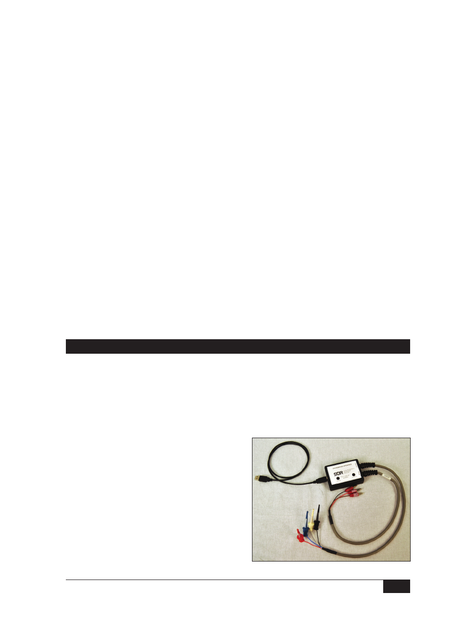
Connect the “Device Cable” to the leads
of the device to be calibrated.
n
Black clip lead labeled “(-)” to the
black “(-)” wire of the device.
n
Red clip lead labeled “(+)” to the
red “(+)” wire of the device.
n
White clip lead labeled “Comms”
to the white wire of the device cable.
n
Blue clip lead labeled “V out” to the
blue “(1-5VDC Output)” wire of
the device. (required only for 1-5V devices)