5 option: pressure control valve – Martin Christ RVC 2-25 CDplus User Manual
Page 29
RVC 2-25 CD&
5 Set-up and connection
Version 11/2008, Rev. 2.2 of 04/12/2013 • sb
29
Translation of the original operating manual
Pos: 100 /20 0 Ch rist/3 71 RVC-BA (PROJEK TE)/RVC 2- 25 CD plus/0 50 Auf stellu ng u nd Ansc hluss/ 050 -00 50 Optio n: Dr uckste uerv entil und Va kuu mmes sson de @ 8\m od_ 131 590 179 1721 _68 .docx @ 5 050 5 @ 4 @ 1
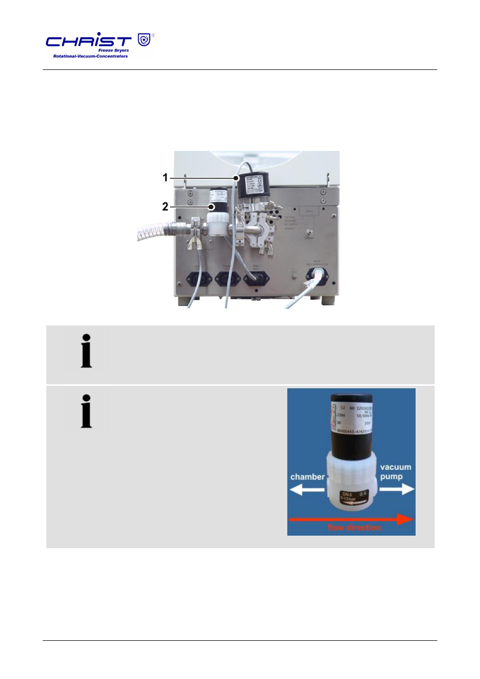
5.5 Option: Pressure control valve
If a pressure control valve and a vacuum sensor are used, they must be
installed between the rotational vacuum concentrator and the vacuum
pump, and they must be connected to the marked IEC C14 connector at
the back of the unit (see chapter 2.1.1 - "Functional and operating
elements").
1
Vacuum sensor
2
Pressure control valve
Fig. 8: Installation of the pressure control valve and the vacuum sensor
NOTE
Observe the installation direction of the pressure control valve!
NOTE
Only for GEMÜ solenoid valves,
type 52 (DN6):
GEMÜ solenoid valves of this type
must be installed contrary to the
marked flow direction (see the
illustration)!
Fig. 9: Gemü solenoid valve, type 52 (DN6)
Pos: 101 /01 0 Univ ersal mod ule/ Sei tenwe chsel @ 0\ mod _12 021 1624 431 2_0 .docx @ 1 05 @ @ 1