Hanna Instruments HI 720 Series User Manual
Page 6
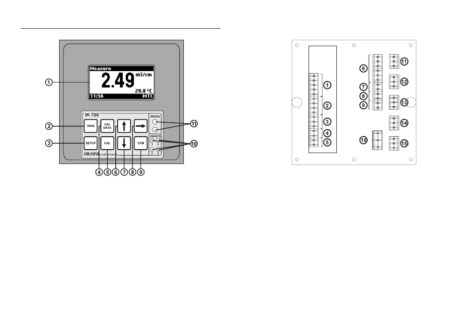
10
11
1.
Connections for conductivity probe
2.
Connections for Pt100/Pt1000 temperature sensor
3.
Digital Transmitter input
4.
Hold input
5.
Advanced Cleaning input (optional)
6.
RS485 output terminal
7.
Hold output
8.
Analog output #1
9.
Analog output #2 (optional)
10.
Power supply input
11.
Relay #3 - for Advanced Cleaning feature (optional)
12.
Relay #4 - for Advanced Cleaning feature (optional)
13.
Relay #1 - first dosing terminal
14.
Relay #2 - second dosing terminal (optional)
15.
Alarm relay
FUNCTIONAL DESCRIPTION
1.
Graphic display (128 x 64 dots)
2.
DIAG key, to enter/exit diagnostic mode; to change the conductivity or
concentration range while in setup or calibration mode
3.
SETUP key, to enter/exit setup mode
4.
CAL DATA key, to enter/exit last calibration data viewing mode
5.
CAL key, to enter/exit calibration mode
6.
key, to increase current digit by 1, shift to next option, or move to next
record while in diagnostic mode
7.
key, to decrease current digit by 1, shift to previous option, or move to
previous record while in diagnostic mode
8.
key, to cyclically change temperature compensation option for conduc-
tivity readings: compensation enabled (temperature is continuously dis-
played) or compensation disabled (actual reading). Only displayed values
are affected by this key; control and logging are not affected.
9.
CFM key, to confirm current choice
10.
Contact LEDs, each turns on when the corresponding relay is energized
11.
Status (red) and alarm (green) LEDs