14 replacement of parts – Glow-worm 24-38CXI Range User Manual
Page 50
50
0020013349-02
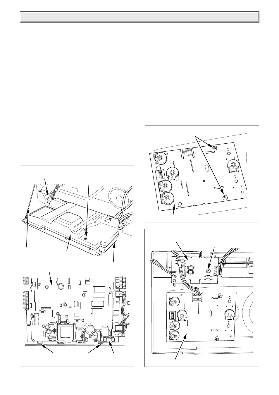
Diagram 14.28
230V CONTROLS
INTERFACE BOARD
USER INTERFACE
RETAINING
SCREW
11419
14 Replacement of Parts
Diagram 14.27
USER INTERFACE
SECURING SCREWS
11417
14.42 Control Box
For access, refer to section 14.43.
Remove relevant plugs and connectors, refer to wiring diagram
13.1.
Withdraw grommets and leads so they are hanging loose.
Unthread the retaining cord and remove the control box by
drawing it outwards away from its retaining slots, see diagram
14.26.
14.43 Fuse, Main PCB - Control Box
For access, refer to section 14.43.
The fuse is located at bottom right hand side of the PCB, see
diagram 13.1 or 14.26.
14.44 User Interface
Refer to section 14.38 for access.
Remove electrical plug.
Remove the securing screws, see diagram 14.27.
Withdraw the board.
When replacing the board refer to instructions supplied with
replacement PCB on setting it up.
14.45 230V Controls Interface
For access, refer to section 14.38.
Disconnect the electrical connection from the 230V controls
interface board and the electrical connection from the Main
PCB.
Remove the 230V controls interface retaining screw.
Remove the 230V controls interface board, see diagram 14.28.
14.46 Condense Drain
For access, refer to section 14.1.
Refer to diagram 14.29.
Remove the clips securing the flexible tubes to the siphon
adapter by twisting the clips slightly to disengage the clip jaws
from each other.
Remove black flexible tubes from siphon adapter.
Lift off the siphon adapter.
Diagram 14.26
9808
REAR PANEL
TORX
SCREWS (3)
CONTROL BOX
PCB RETAINING
CLIPS
RETAINING
CORD
RETAINING
SLOTS
12411
FUSE
MAIN PCB